Phase II - Carcass Construction
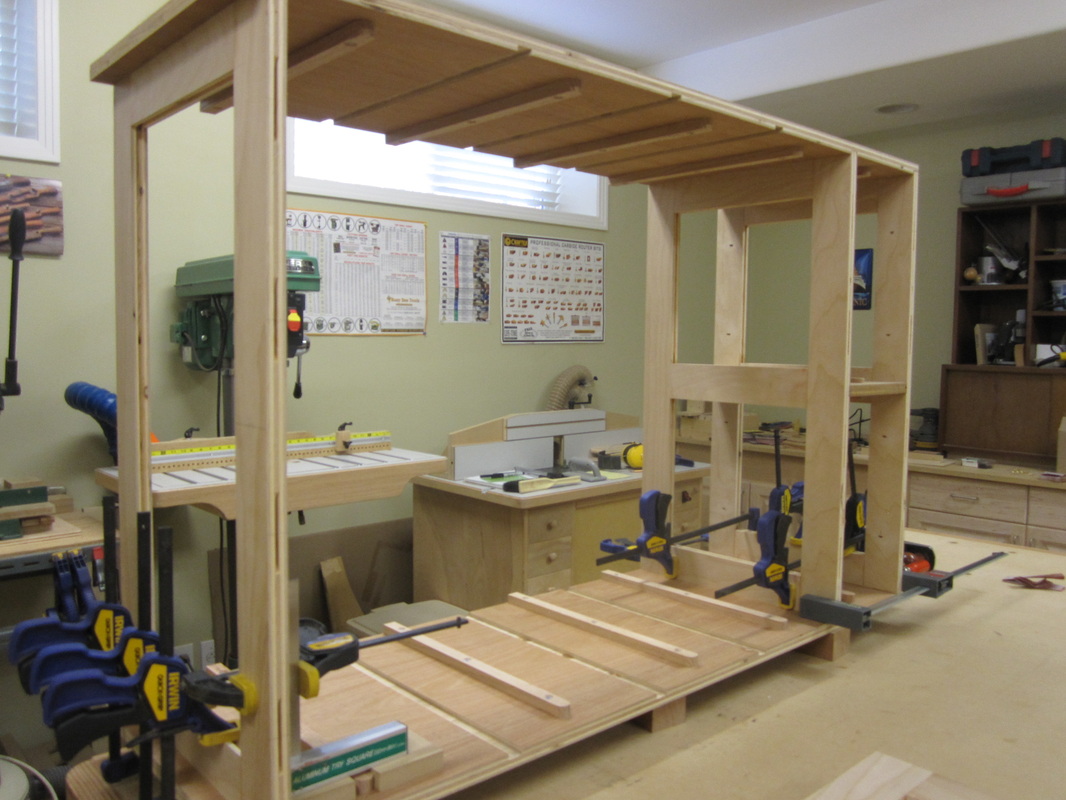
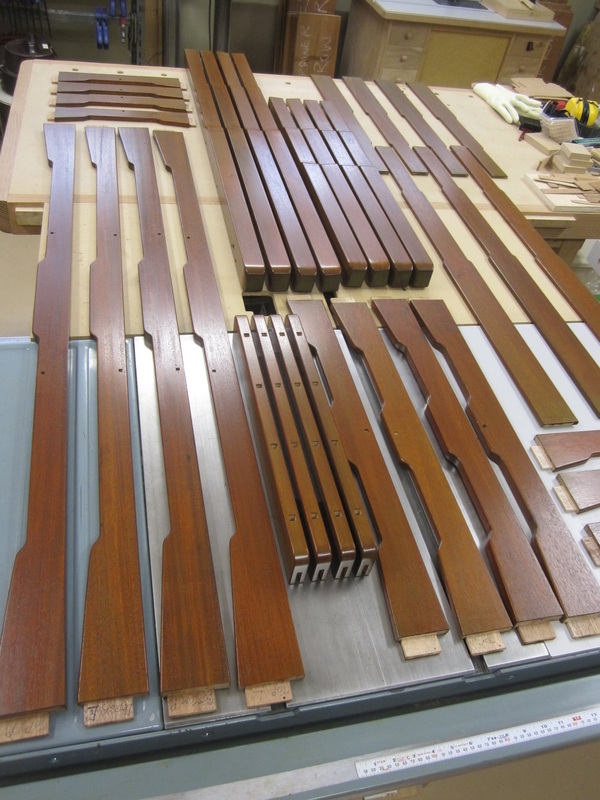
Similar to the night stands, carcass construction for the dresser and chest began with making frames to act as dividers for the rows of drawers as well as a top and bottom frame, all of which are attached to the sides to create the main body of the piece. The frames are constructed of 2-1/2” wide plywood strips joined with groove and stub-tenon joinery.
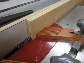
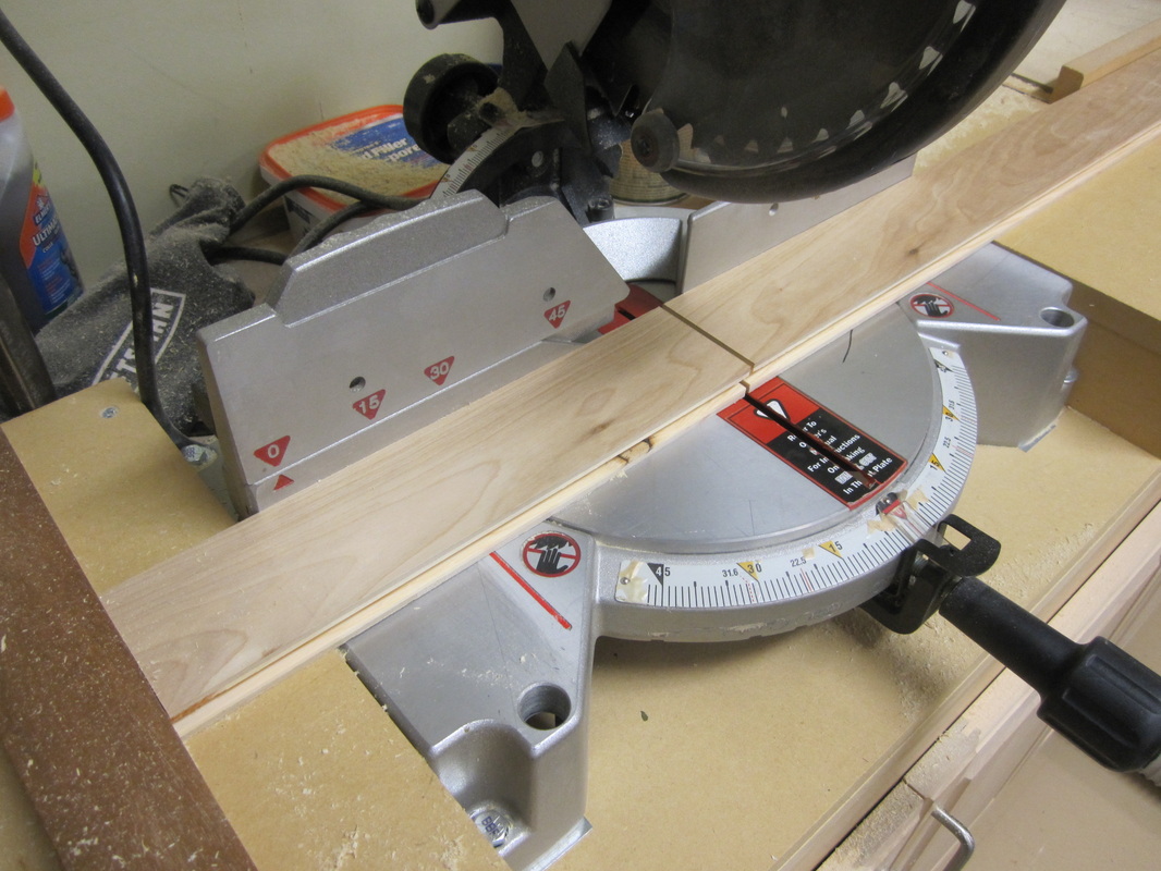
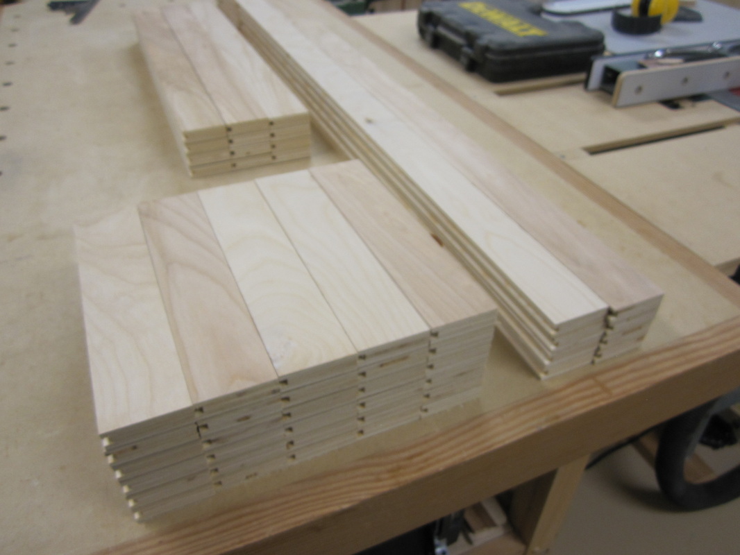
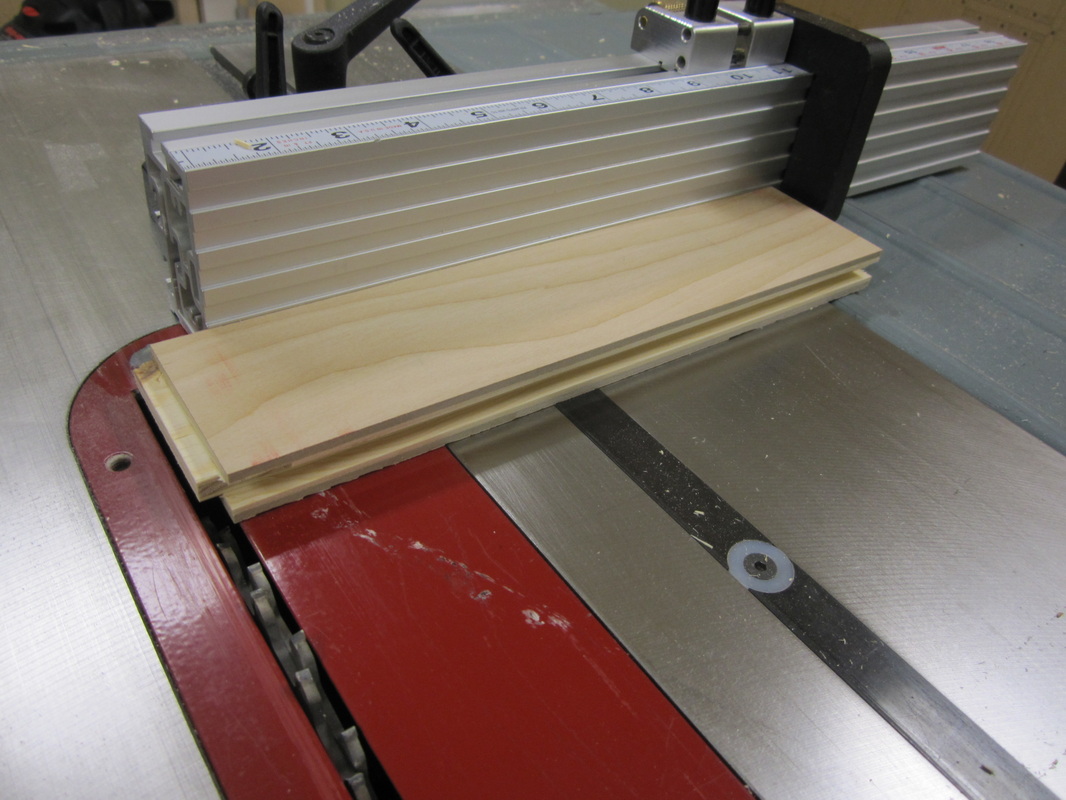
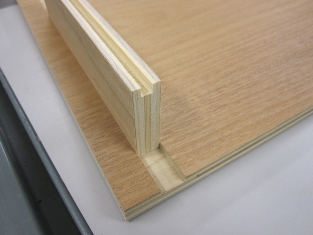
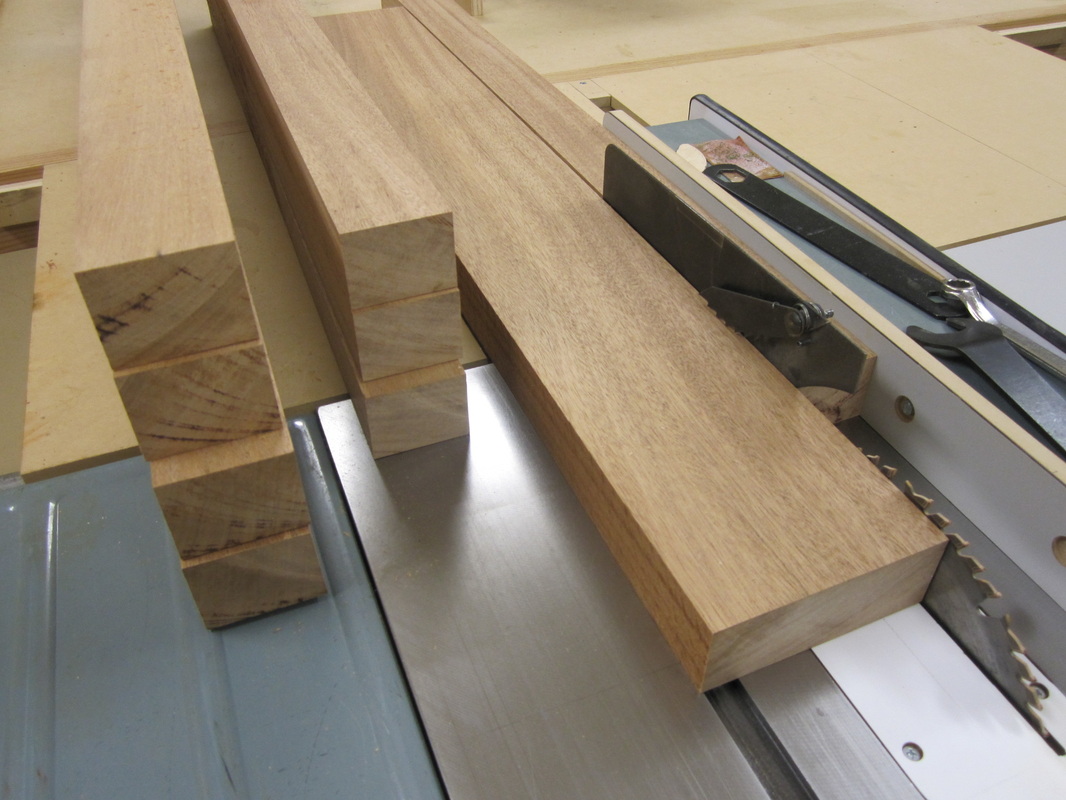
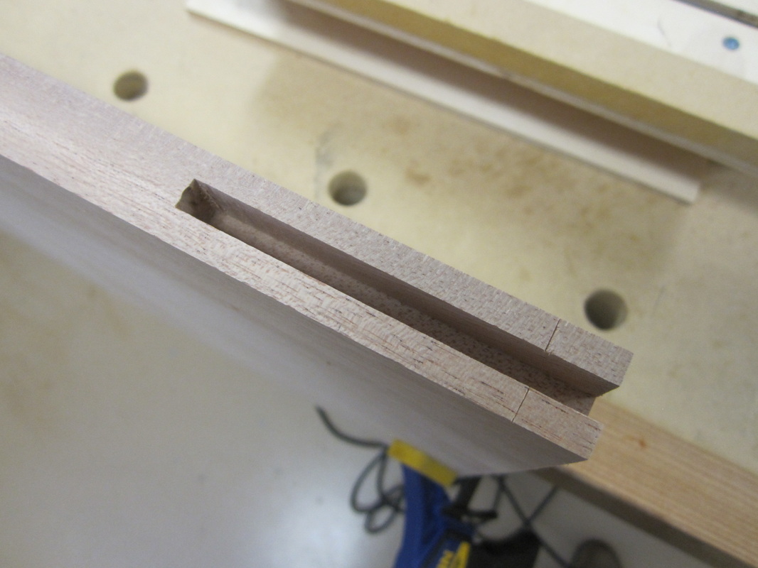
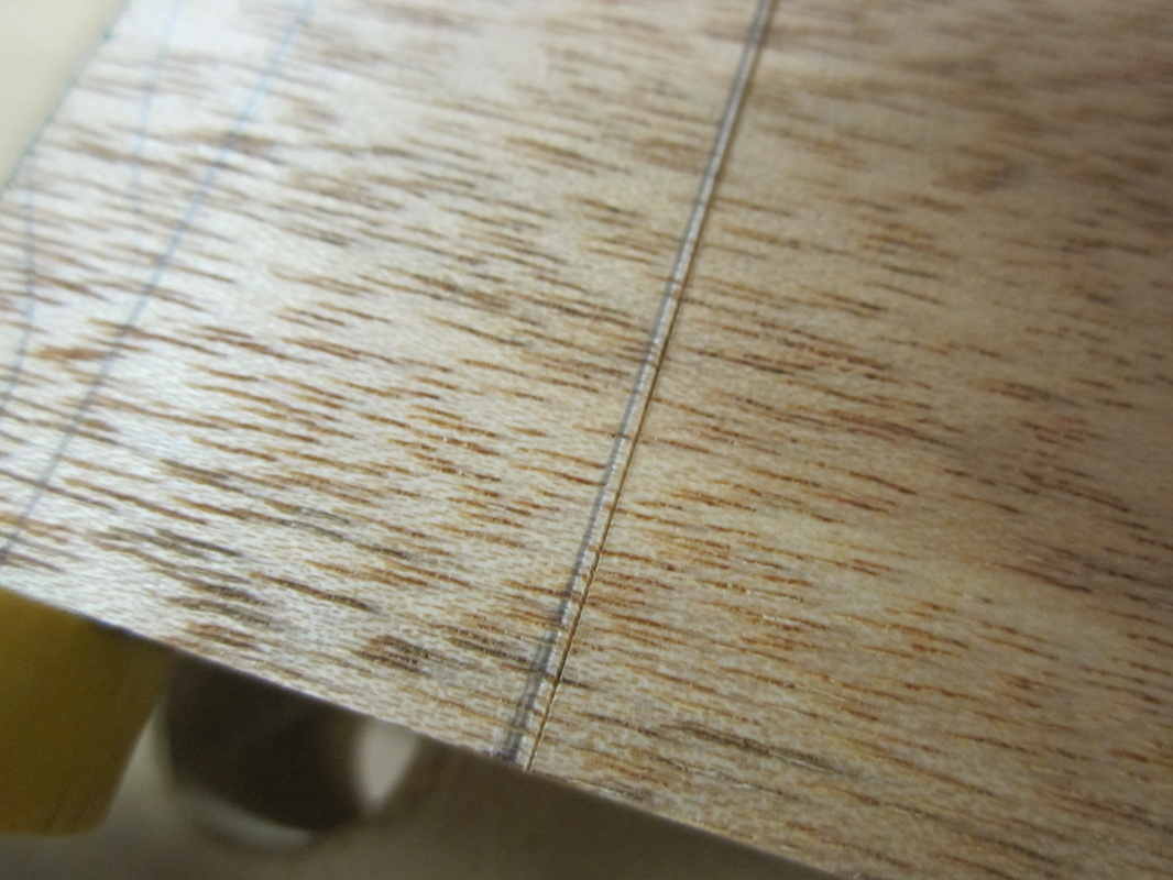
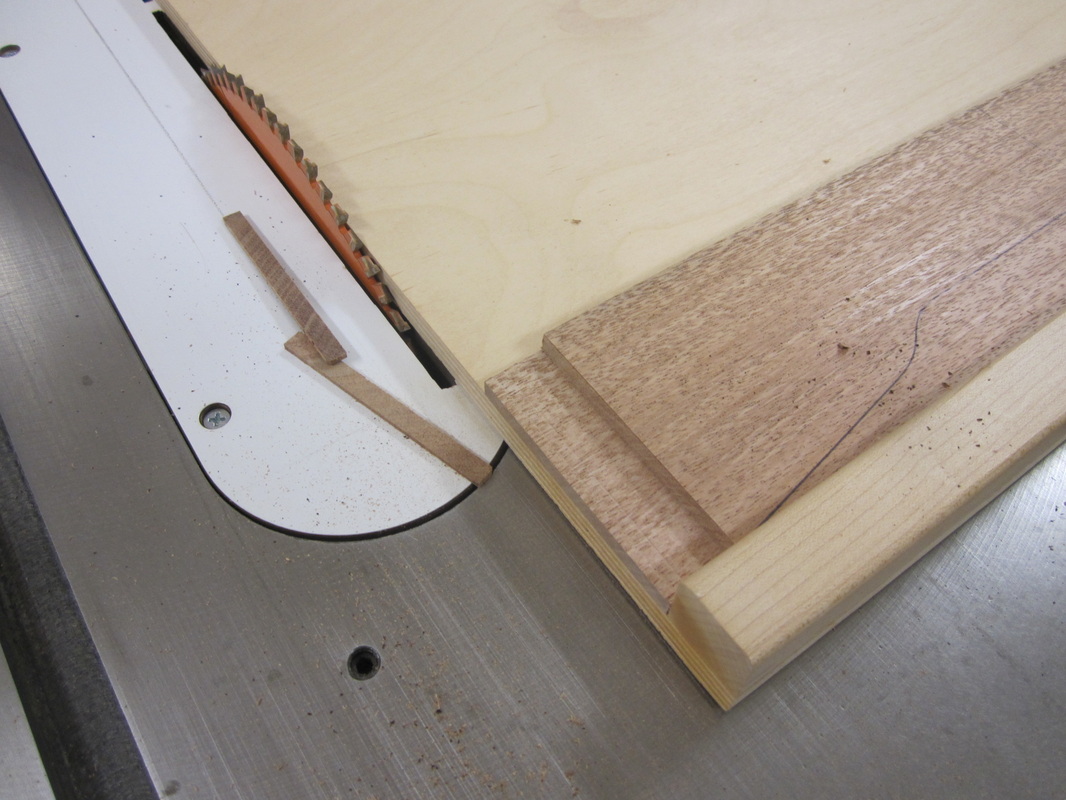
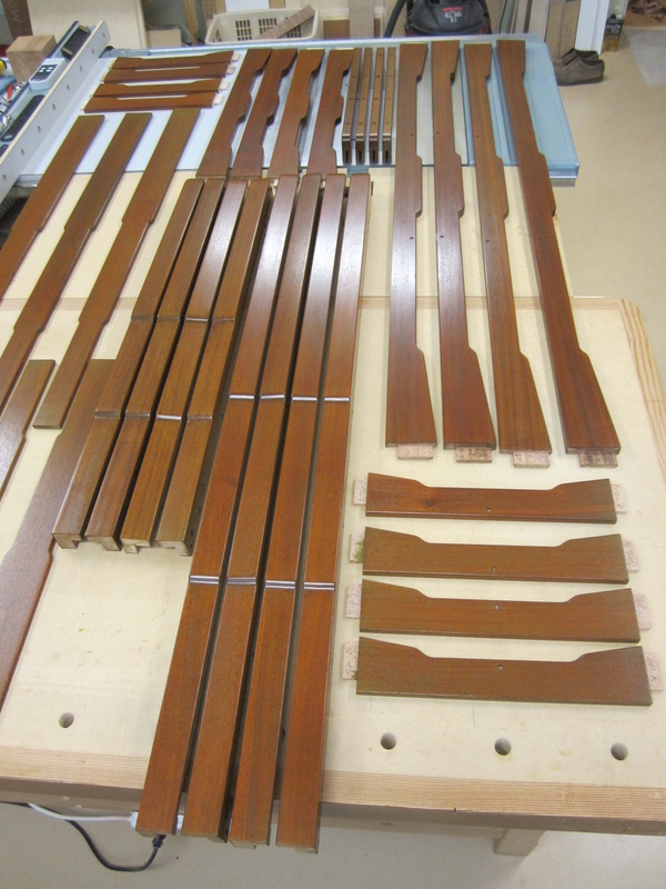
Grooves are cut at the table saw in two passes, turning end-for-end to ensure the groove is centered. The pieces are then cut to length allowing for the stub-tenons that will fit into the grooves.
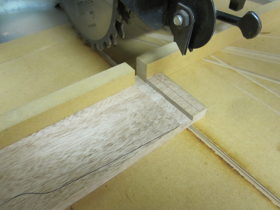
The stub-tenons are also cut at the table saw and, since the dresser and chest are the same depth, all the pieces with stub-tenons can be cut with the same set-up.
Grooves are cut at the table saw in two passes, turning end-for-end to ensure the groove is centered. The pieces are then cut to length allowing for the stub-tenons that will fit into the grooves.
The stub-tenons are also cut at the table saw and, since the dresser and chest are the same depth, all the pieces with stub-tenons can be cut with the same set-up.
|
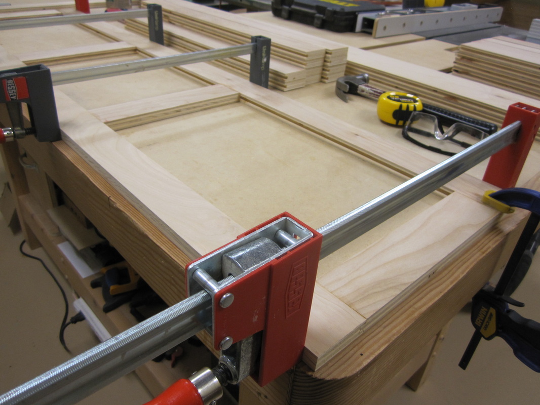
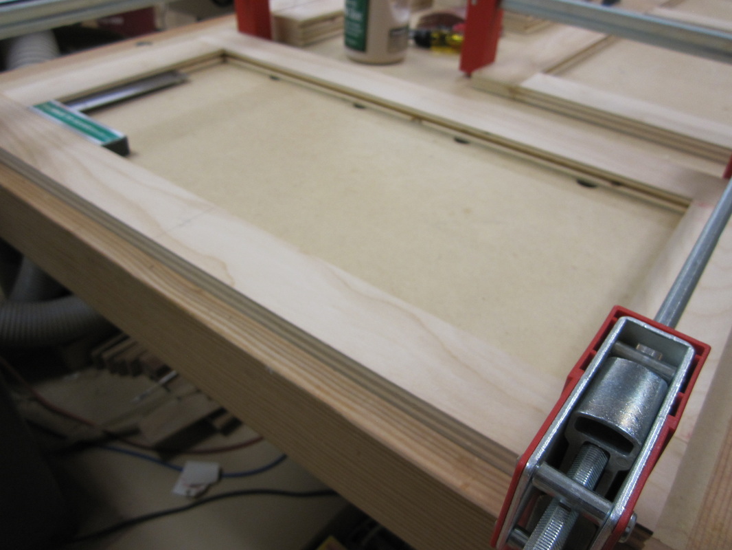
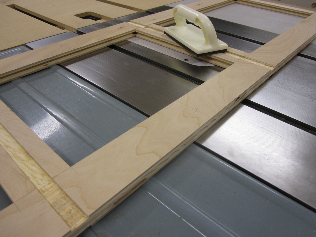
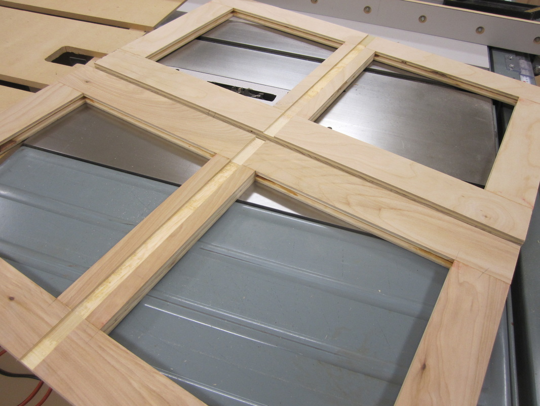
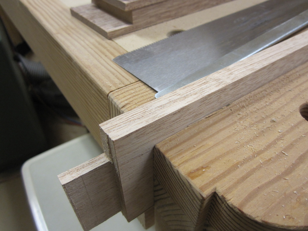
The frames are assembled with glue and clamps, checking to ensure they are square. |
|
|
|
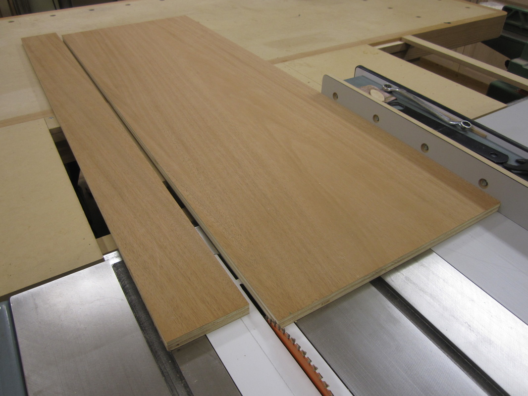
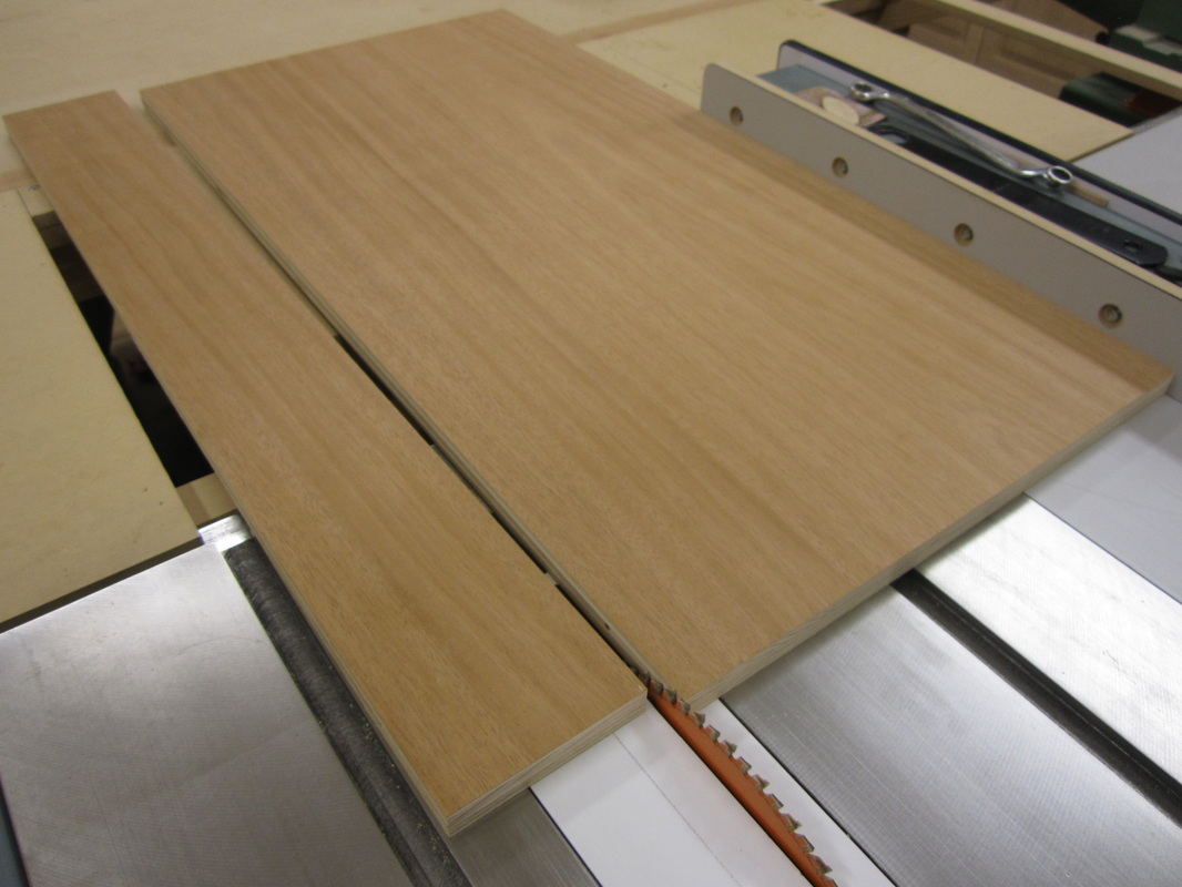
Then the sides are cut to size at the table saw, the long ones for the chest and the shorter ones for the dresser. |
|
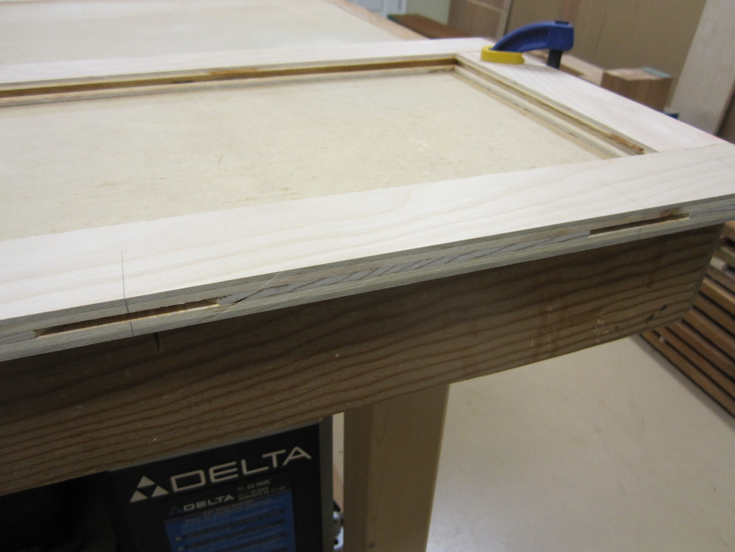
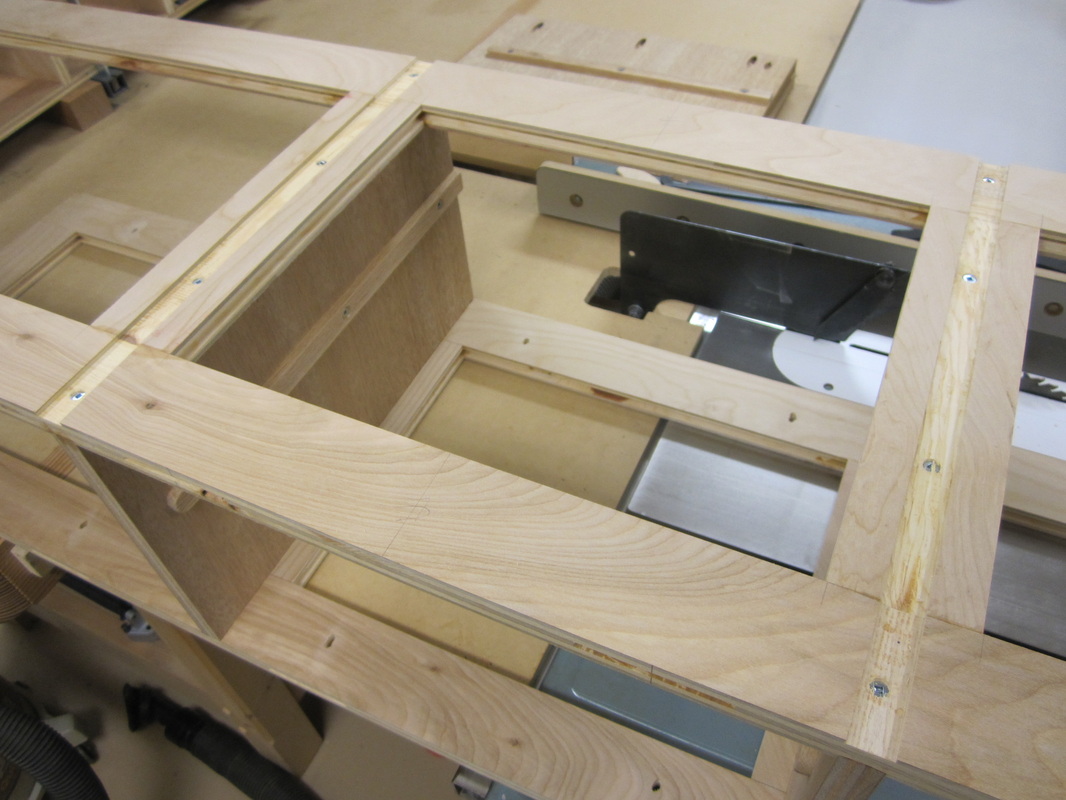
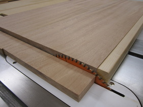
Next, dados are cut on the inside faces of the sides to accept the divider frames that space them apart. The dados are carefully sized to match the thickness of the plywood, about 23/32”, using a test set-up initially before the final cuts. Dados are also cut in the divider frames for vertical dividers that separate the drawers in each row of the dresser. The top and bottom frames have these dados on one side only but the two in between require them on both sides. |
|
|
|
Only the top two chest frames require dados for a centre divider. Biscuit slots are cut along the front edges of the frames for future alignment and attachment of the solid wood facing strips as well as strengthening the top and bottom rails. |
|
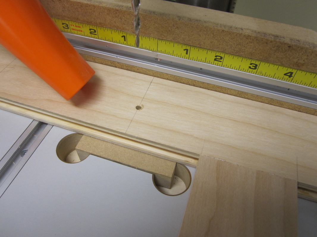
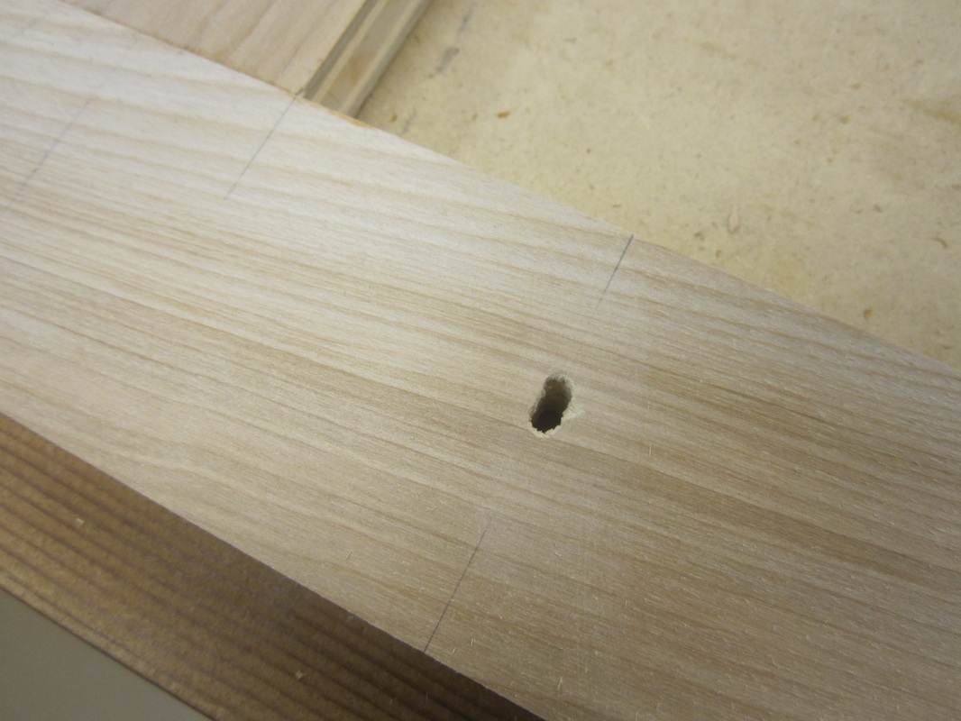
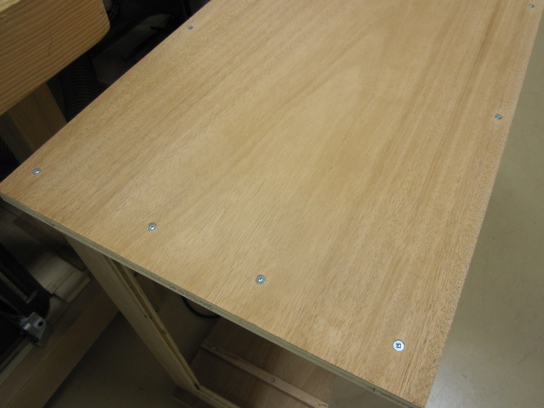
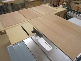
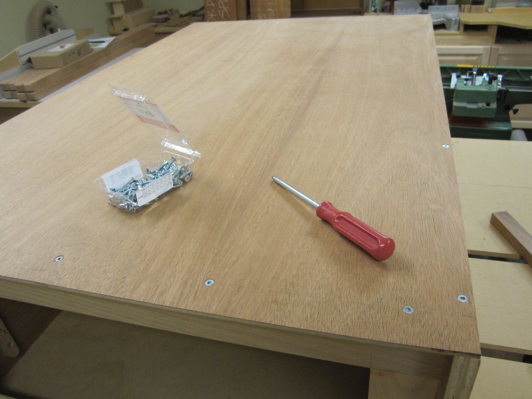
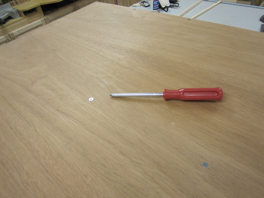
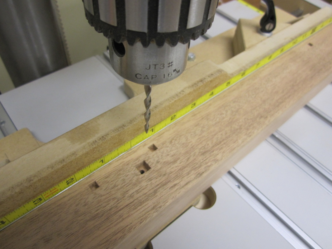
Holes are drilled in the top frame of each piece to facilitate attaching the tops later. The holes are elongated to allow for changes in the width of the solid wood tops due to humidity changes. |
|
|
|
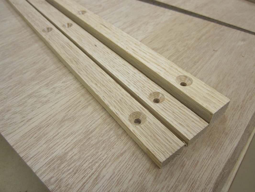
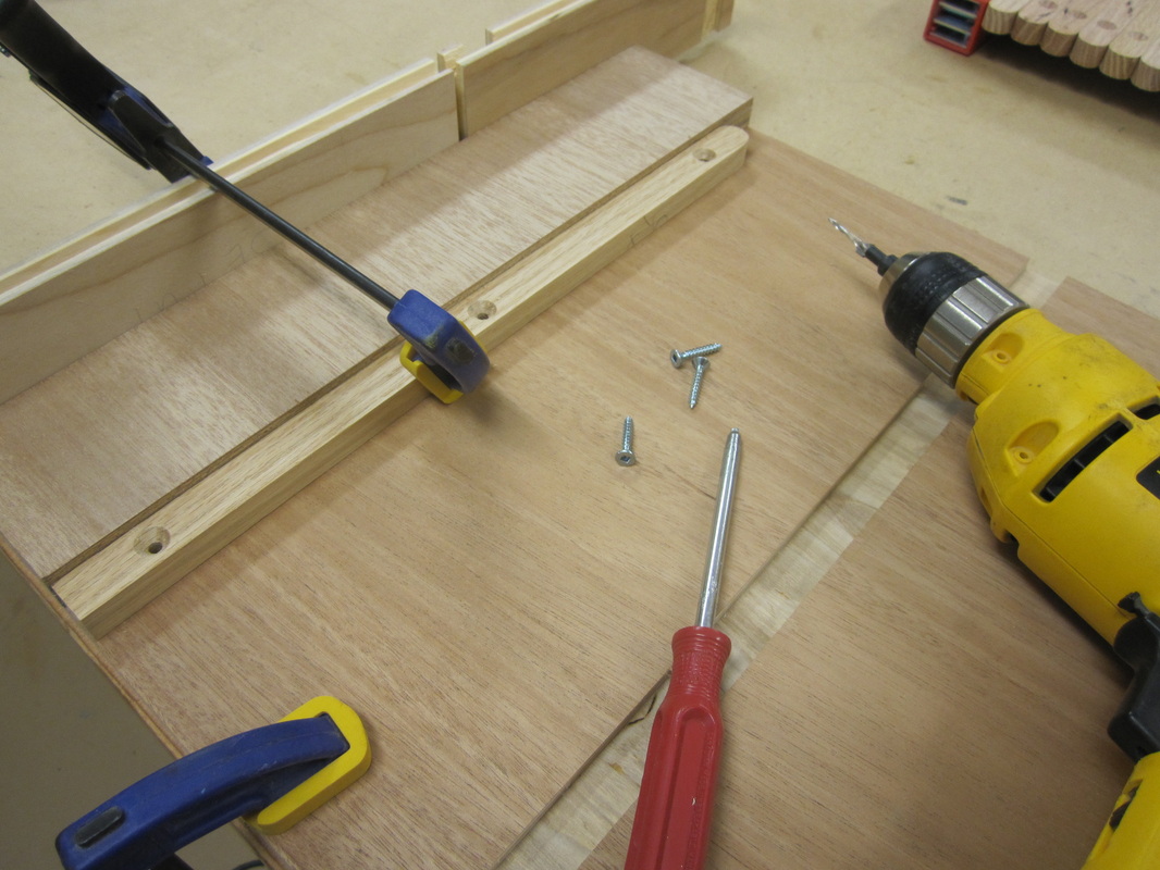
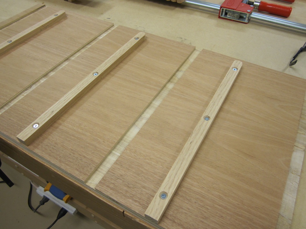
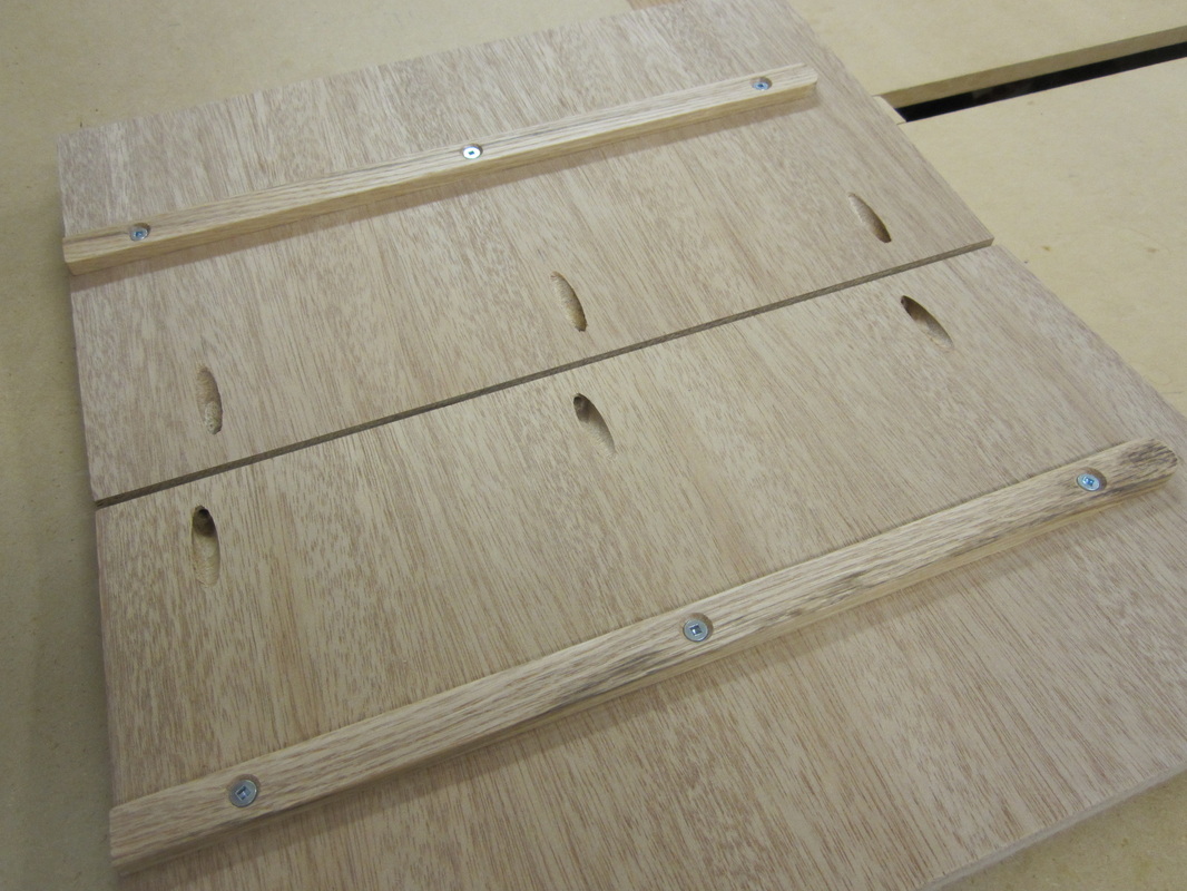
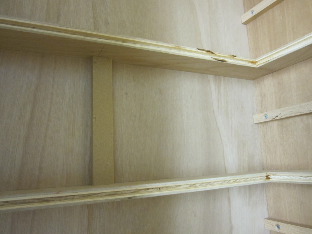
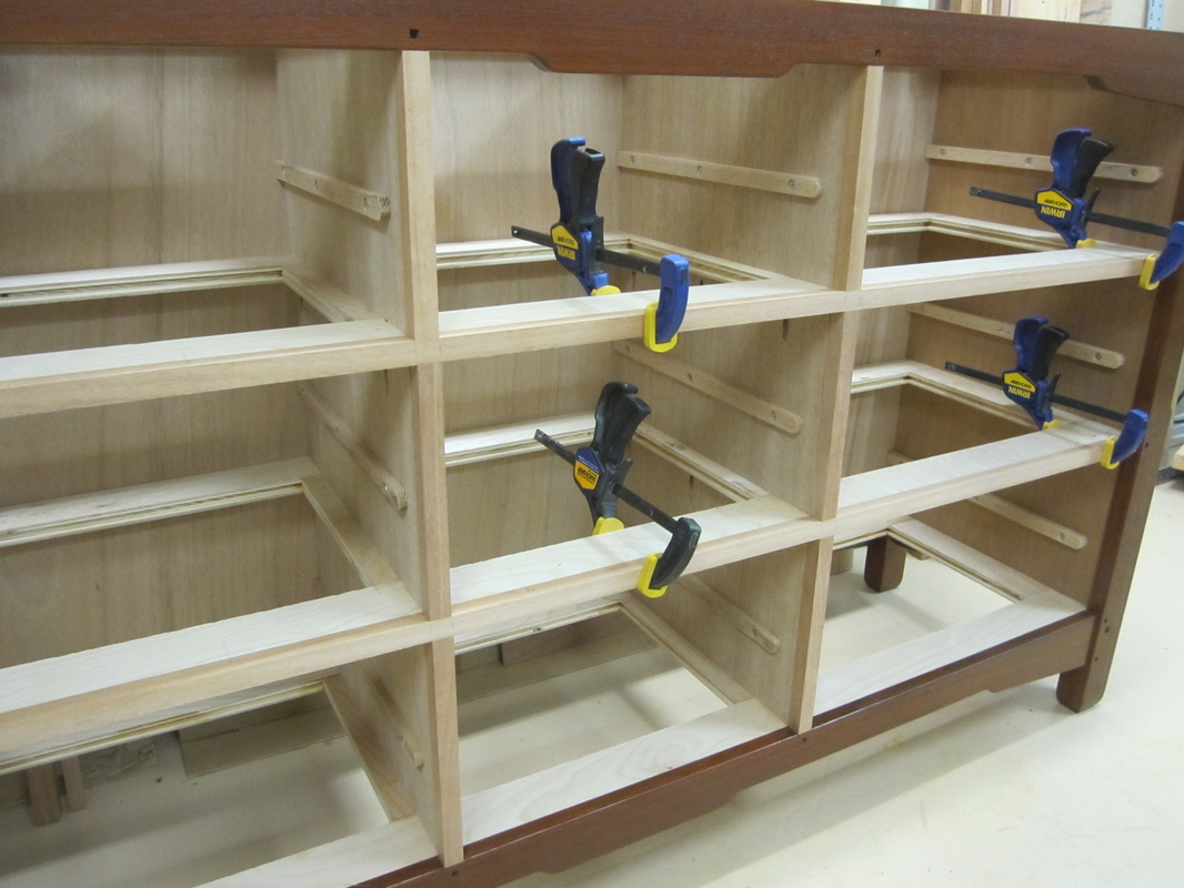
Oak stock is cut and sized to make the drawer slides that attach to the inside faces of the carcass for each piece. The slides that attach to vertical dividers are ½” thick while those that attach to the sides are ¾” thick and all are ¾” deep and the same length. |

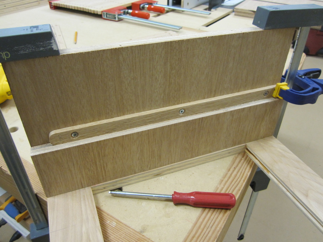
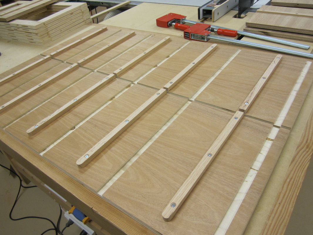
The drawer slides are all positioned using a spacer piece to ensure they are level and parallel to the divider frames. To reduce the possibility of errors when machining the corresponding grooves in the drawer sides, all the slides were positioned using the same spacer. The slides are screwed in place only to allow for possible fine adjustment when fitting the drawers. I decided to attach all the slides before assembly of the frames and sides, as access was better.
Next, the vertical dividers are glued into their respective places in the frames and the frames are dry fitted to the sides to keep the whole assembly square. After the glue sets up, the remaining frames are glued in place and strengthened with screws from the outsides. These will be covered later when the rails and legs are added.
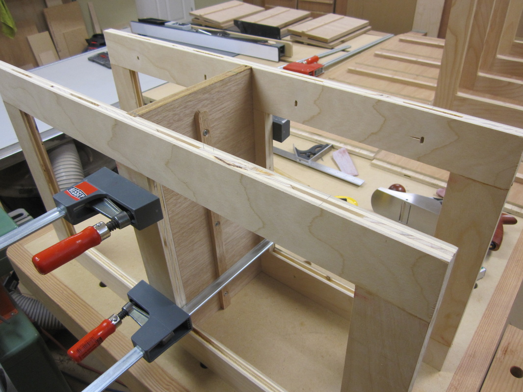
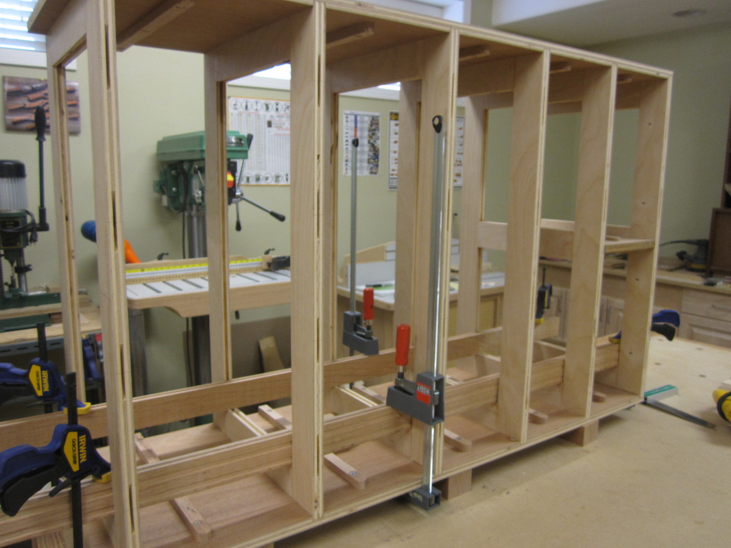
Some additional steps are required to secure the vertical dividers in the dresser, and pocket-hole screws were chosen to reinforce the glued joints that could not be directly accessed from above or below with regular screws.

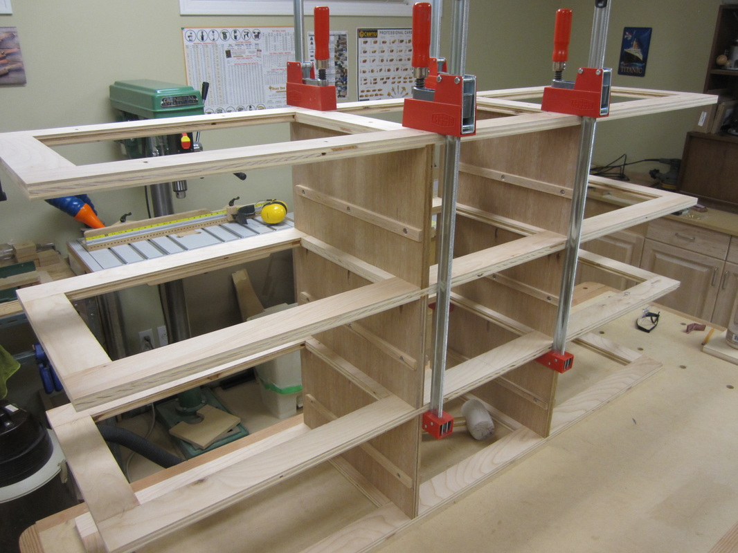
After the sides are glued in place, the plywood parts of the carcasses are essentially complete, except for the back panels.
|
|
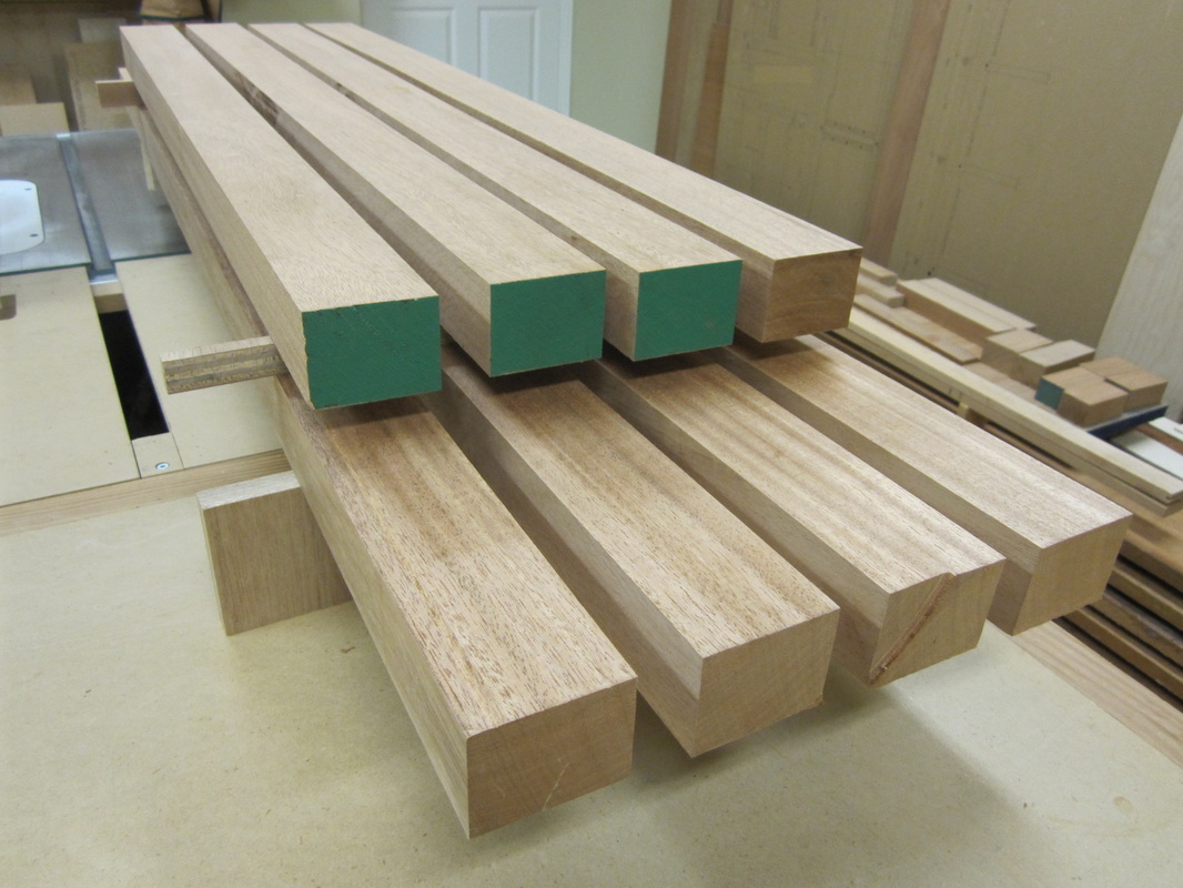
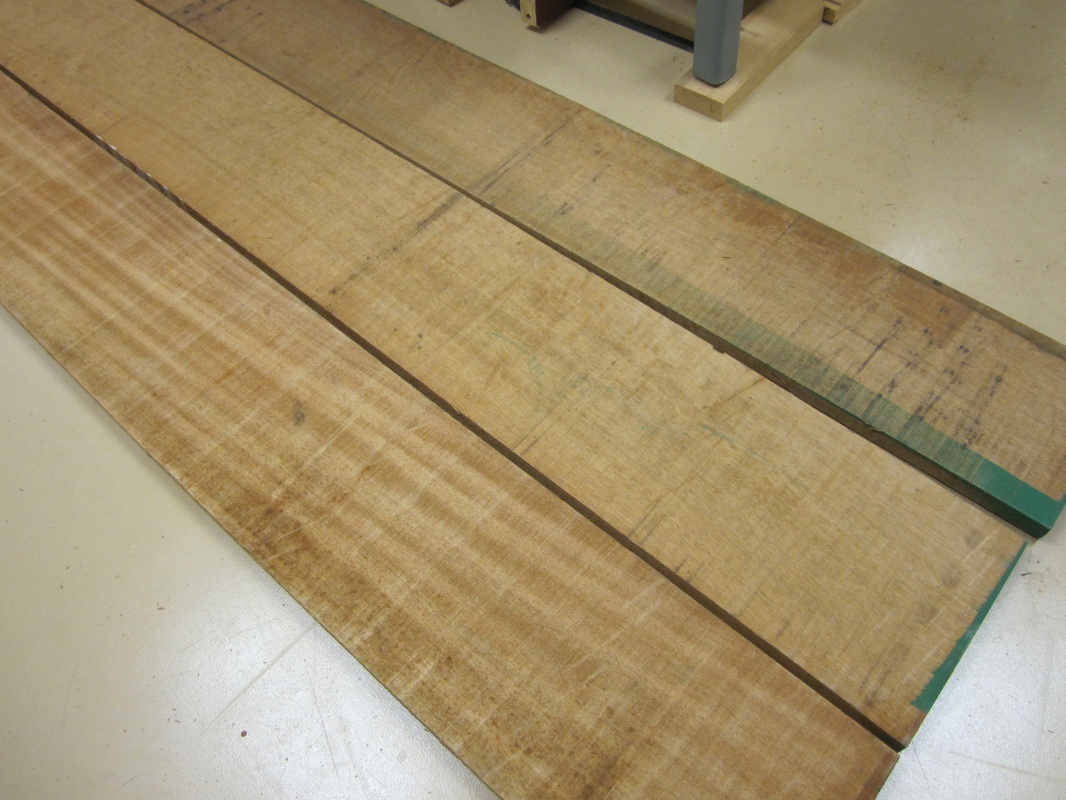
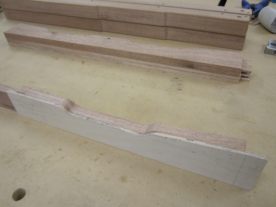
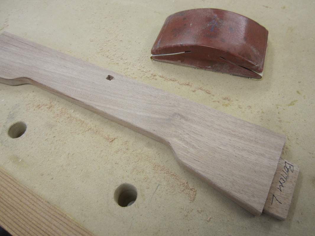
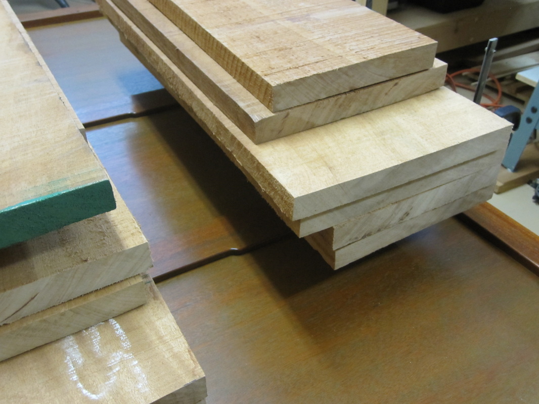
Next, the rough stock for the legs is cut, jointed, planed slightly over-size and stickered to allow the exposed faces to dry again before bringing them down to final dimensions. |
|
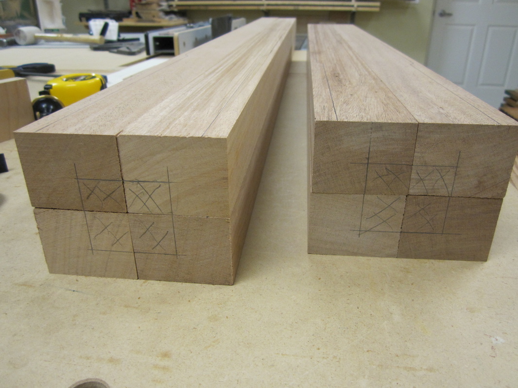
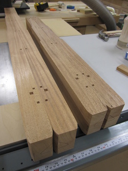
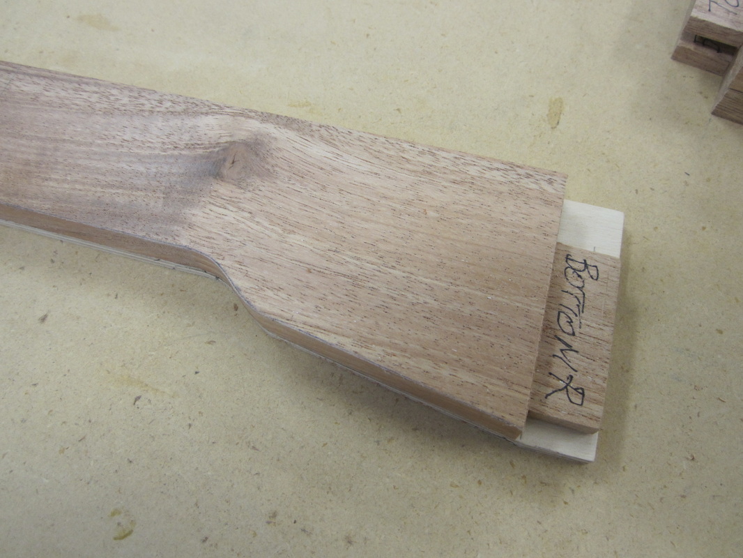
After selecting which faces would look best on the fronts, the leg blanks were marked on the bottom with an orientation triangle and then the profiles from the templates and location of the joinery were marked accordingly. |
|

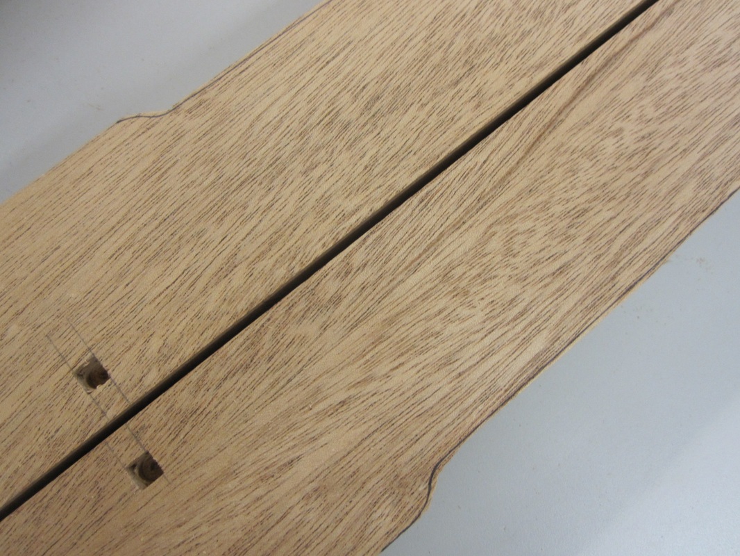
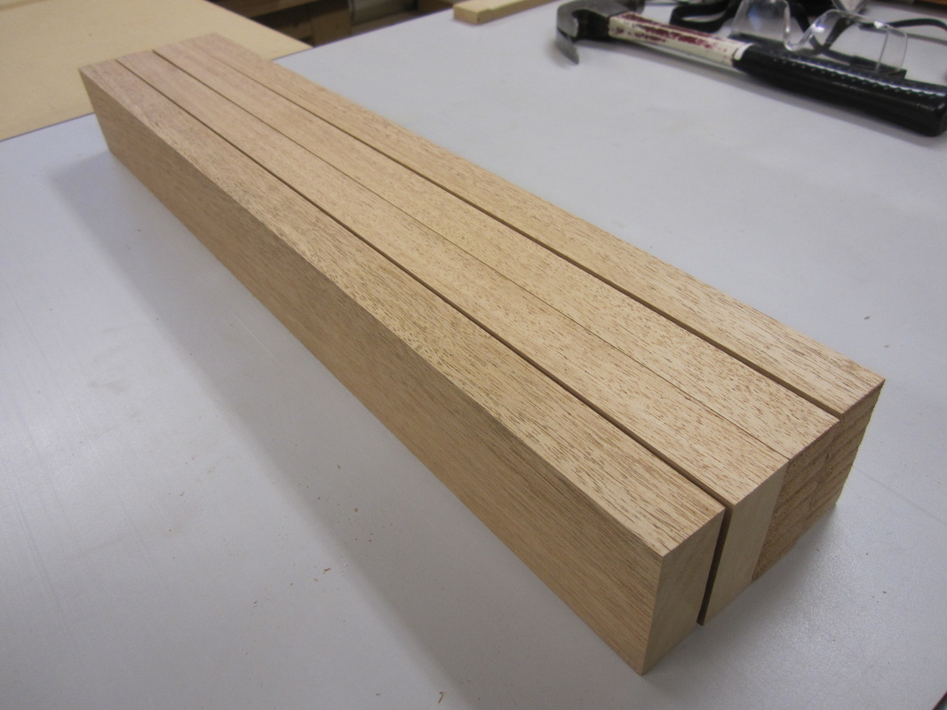
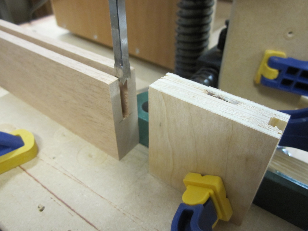
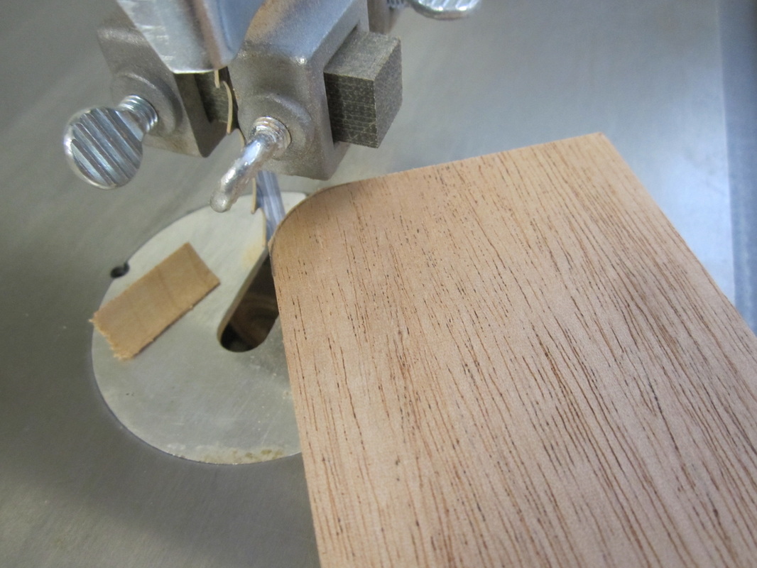
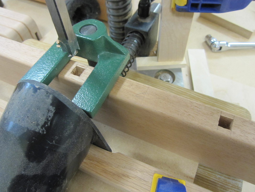
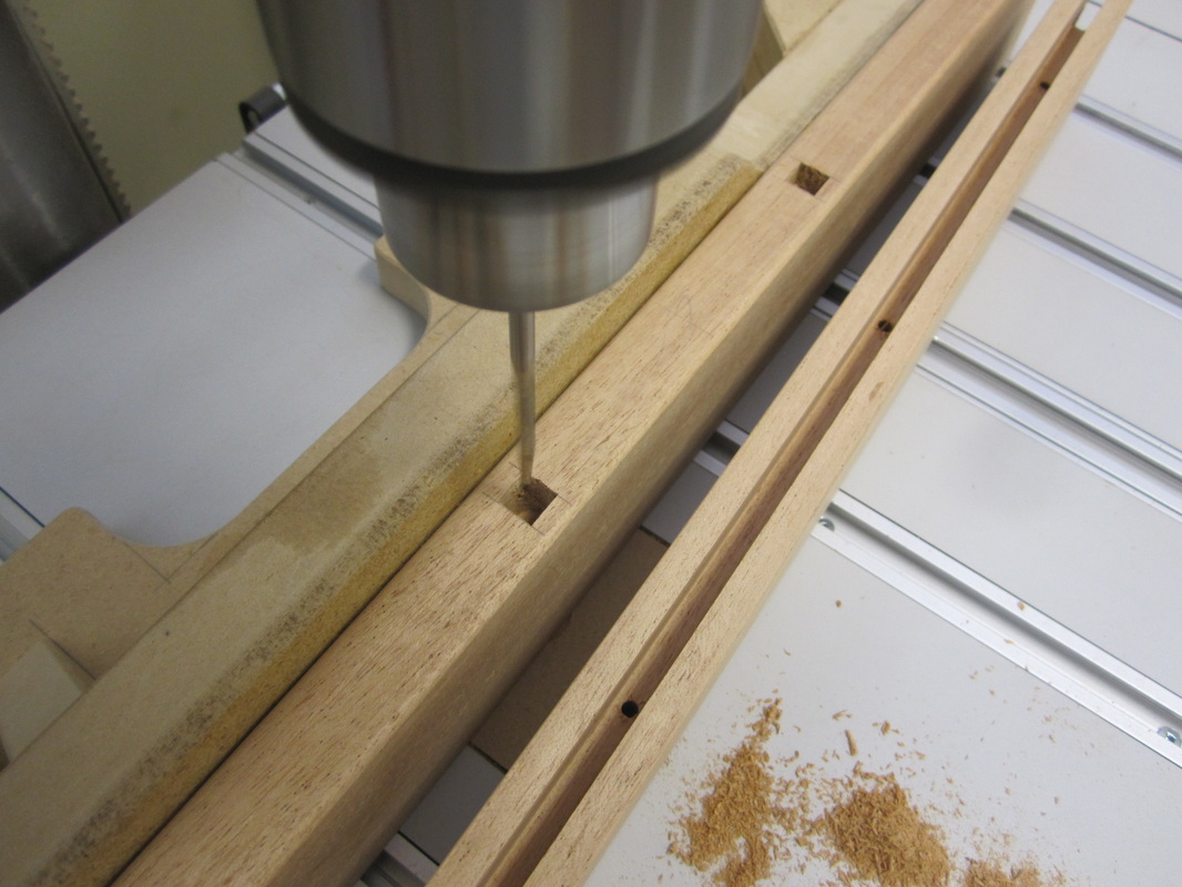
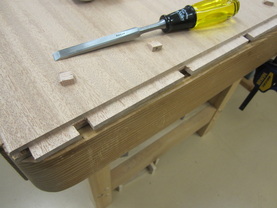
While the blanks still have parallel sides, the mortises for the rails and the holes for the decorative pegs are cut at the mortising machine. Then the inside corners are removed at the table saw using stop blocks to avoid over-cutting beyond the mortises for the bottom rails. The un-cut pieces are removed and squared up with a chisel. The set-up for the front legs is slightly different than for the back legs to accommodate the thickness of the back panel which entirely covers the carcass.


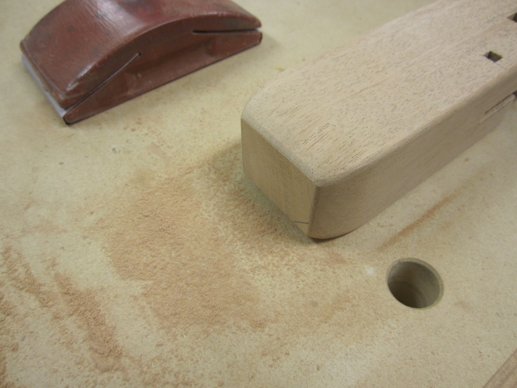
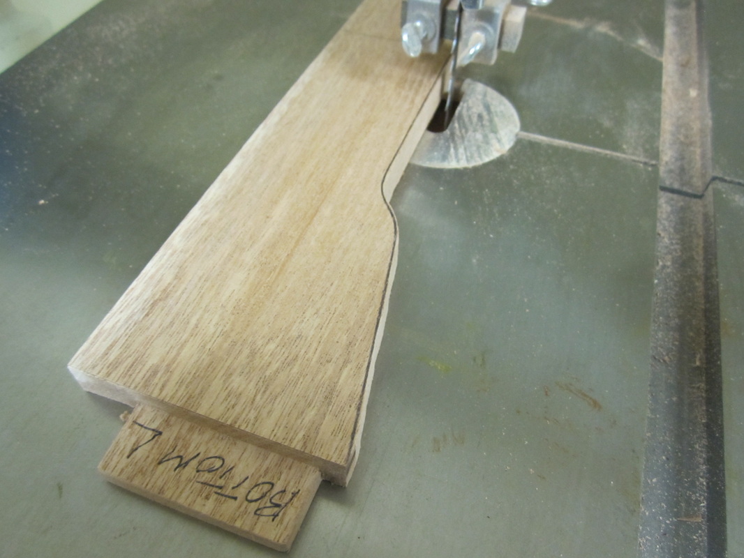
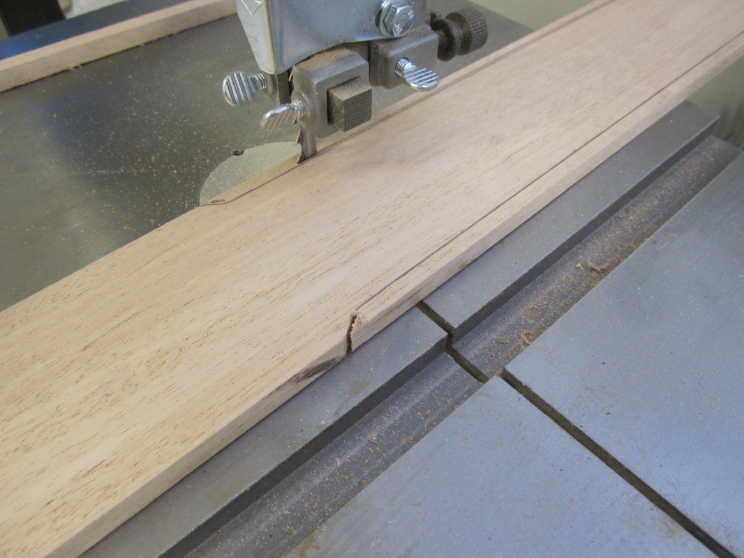
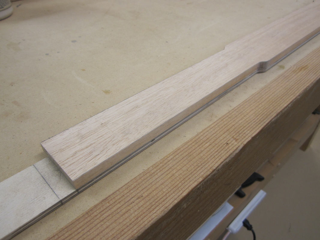
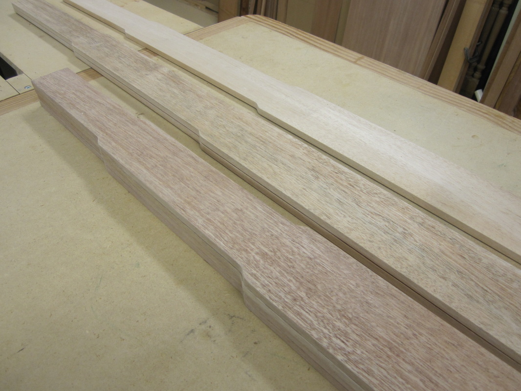
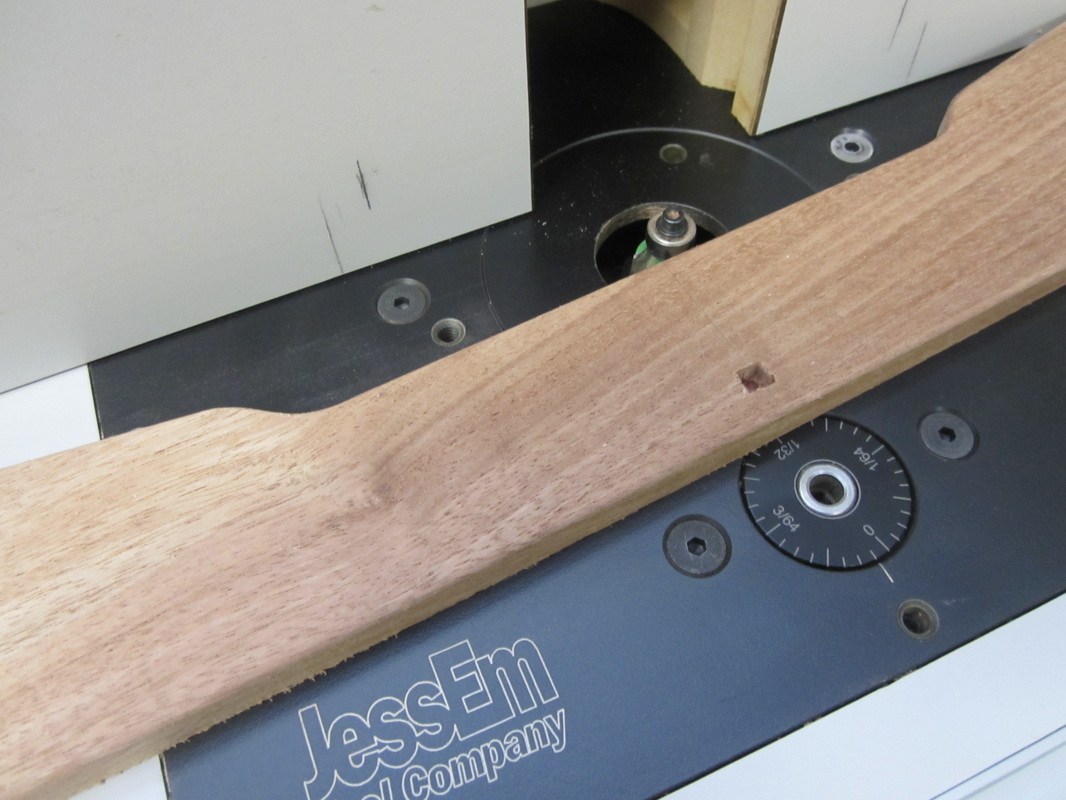
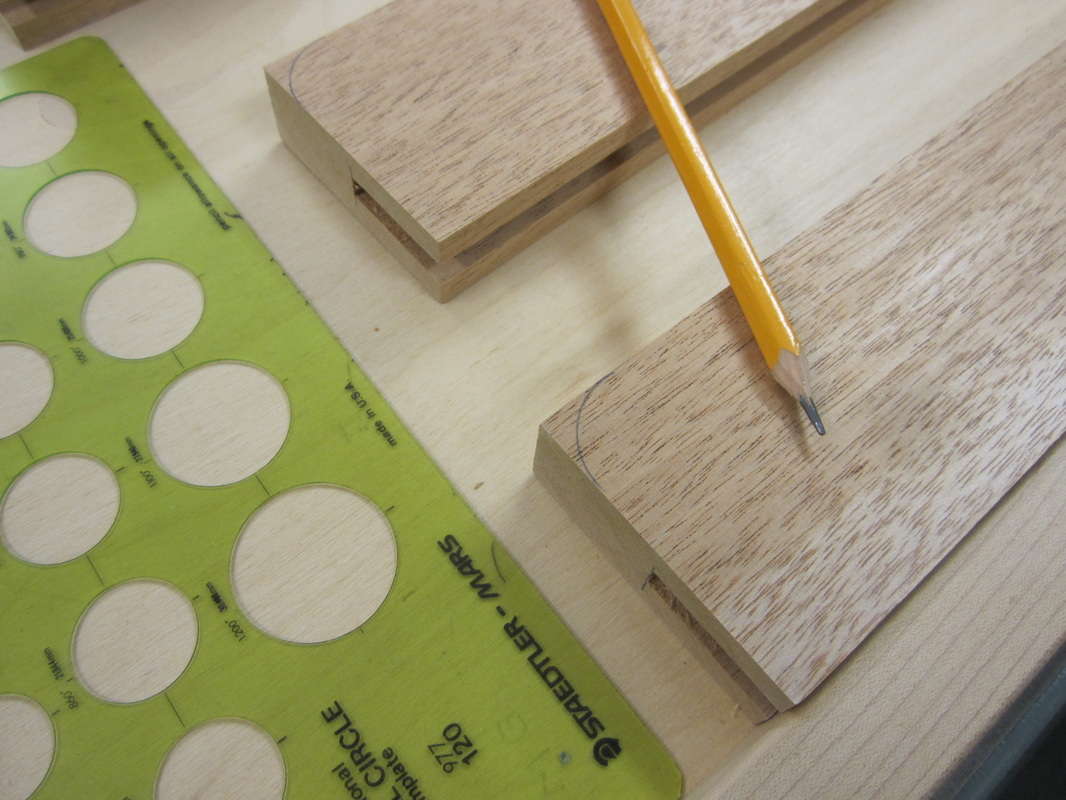
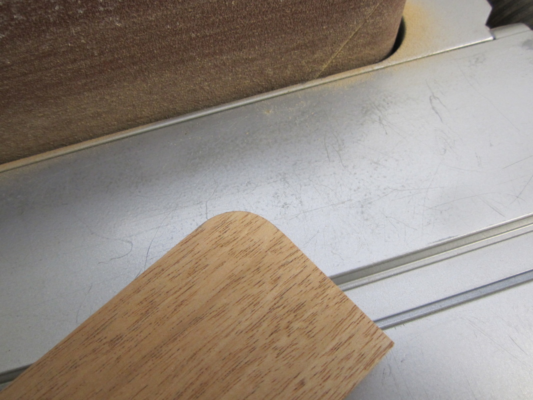
The profiles along the outside edges of the legs are rough cut at the band saw and the templates are attached with double-sided tape so they can be trimmed to the finished profile at the router table. The profile at the bottom of the legs is too wide for my router pattern bit so I used the belt/spindle sander to shape them. The edges are rounded over at the router table with a 1/8” radius round-over bit followed by some hand sanding at the bottoms.
|
|
|


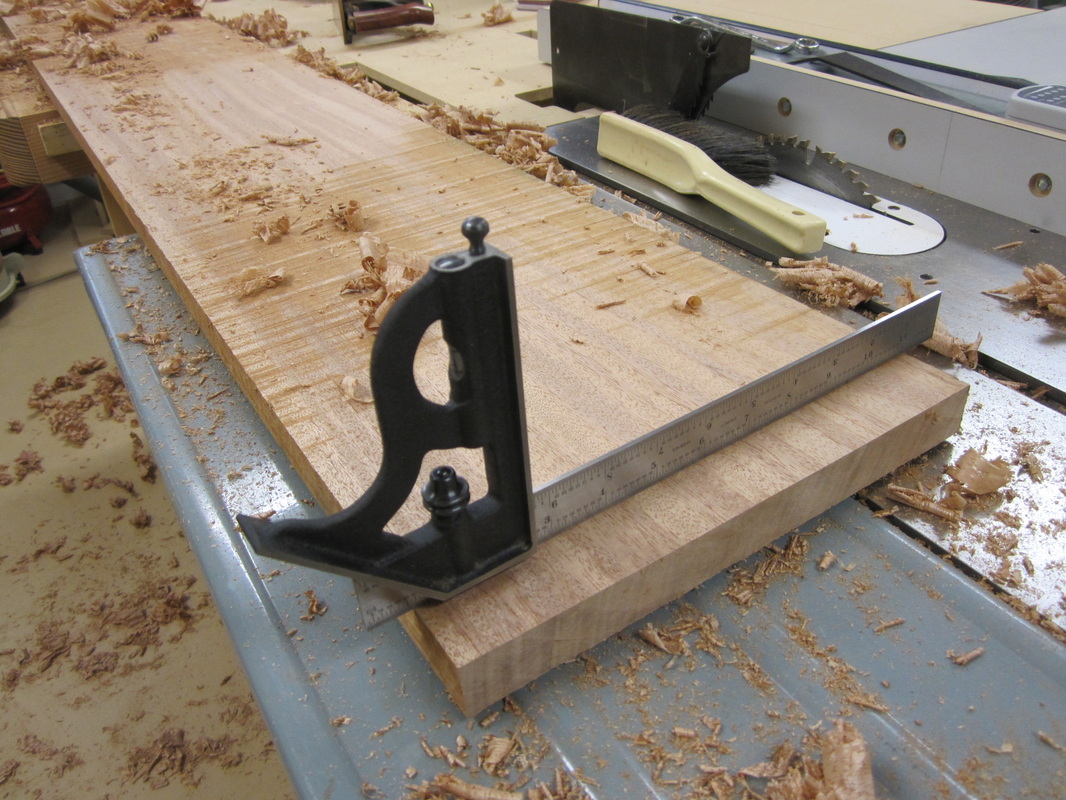
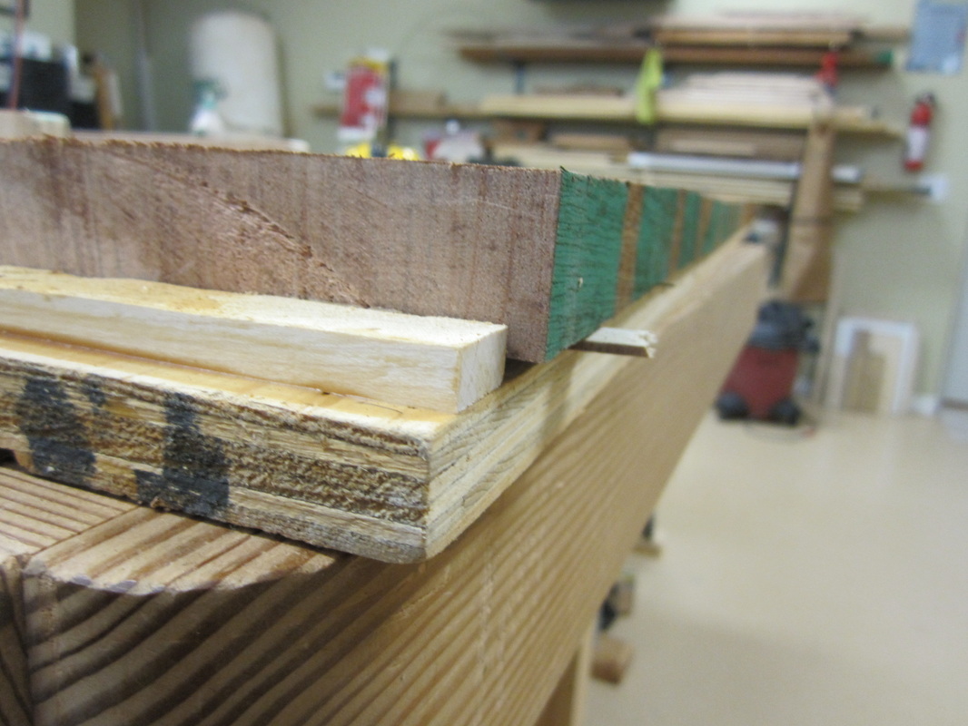
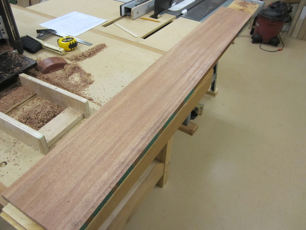
The blanks for the breadboard ends for the tops were rough machined and the process of leveling the stock for the tops began with some hand planning to reduce the twists. I then used a “planing sled” (plywood strip with a cleat at one end) and a number of small wedges or shims to level the board to the plywood while running it through my 12-1/2” planer. I made multiple light passes until I got a smooth surface as a reference before flipping the piece over and repeating the process until the opposite face was smooth and parallel. My intention was to make each top from two pieces, so having only one joint line which I would try to conceal as far as possible.
|
|
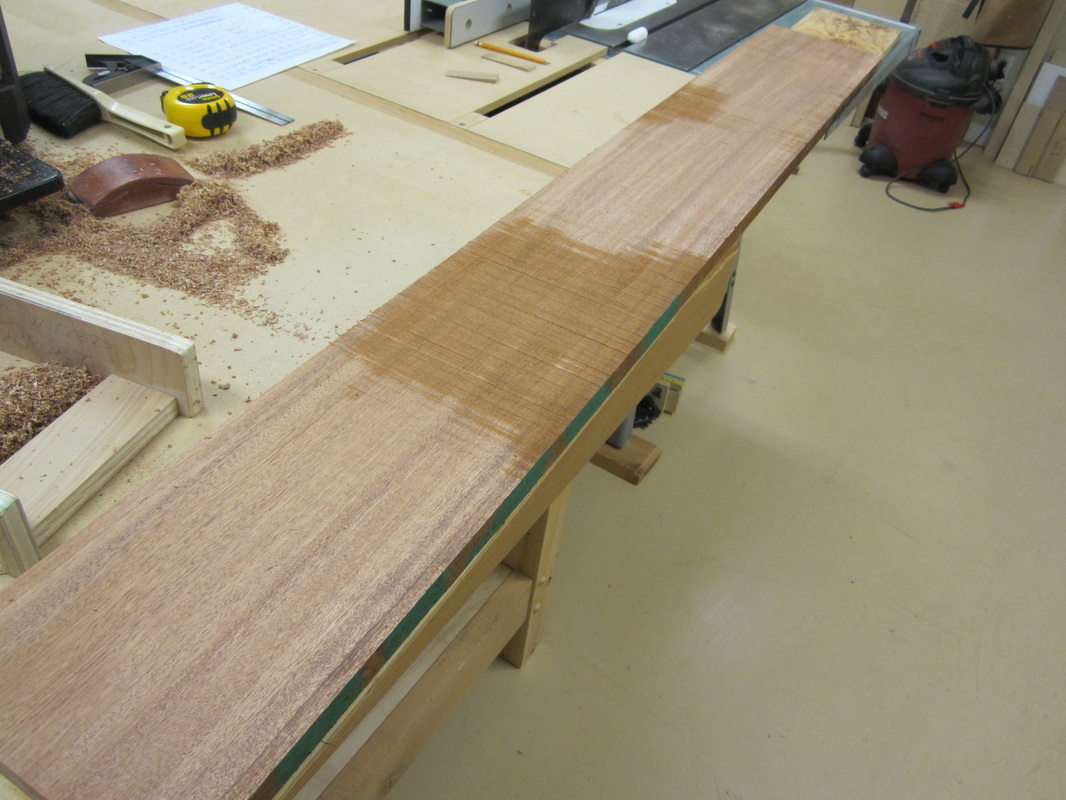
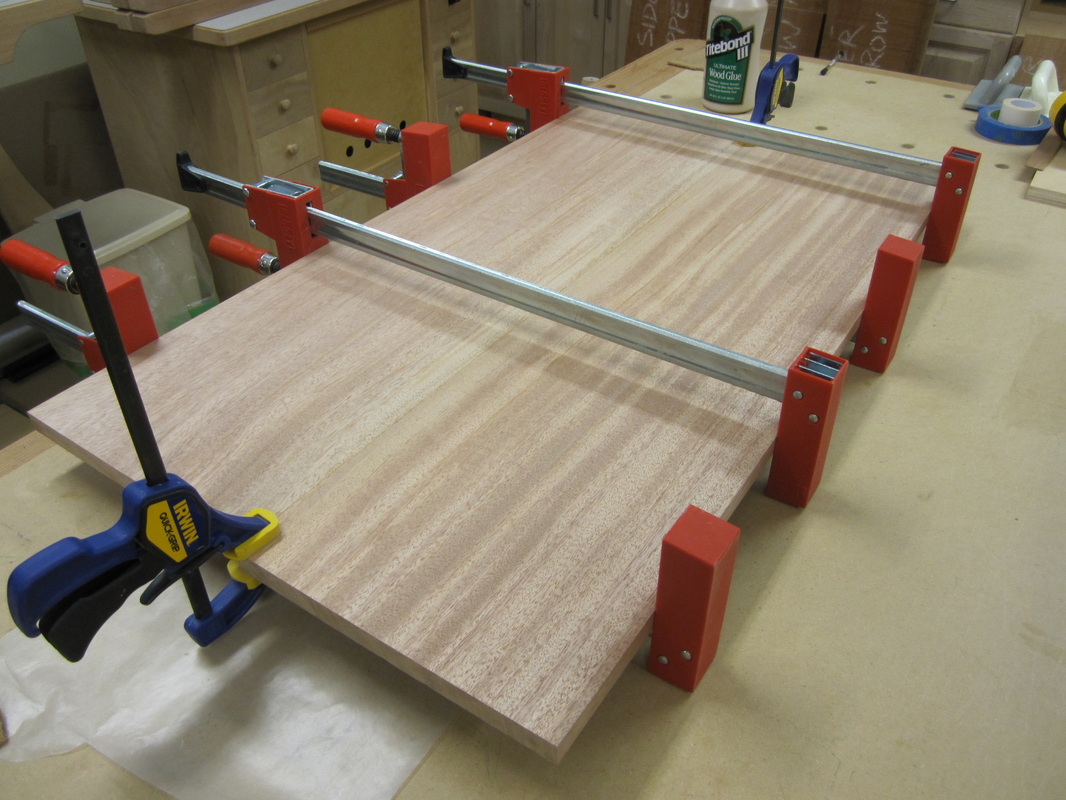
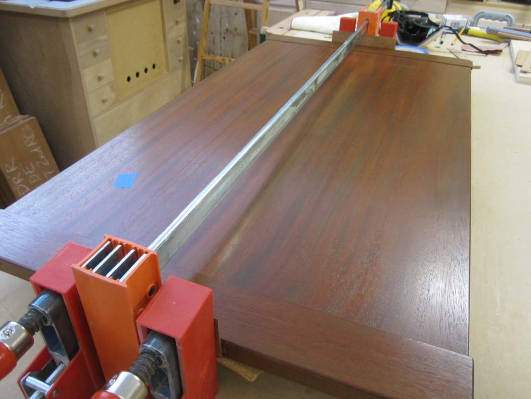
After jointing the edges of the smoothed boards and making them parallel at the table saw, I glued and clamped them up. |

|
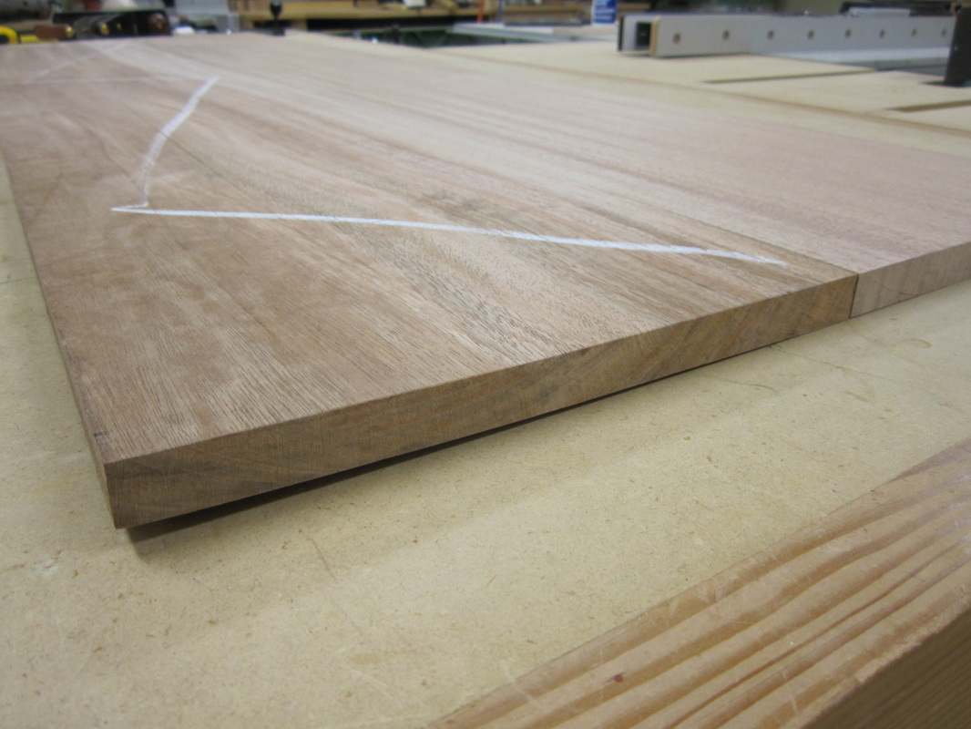
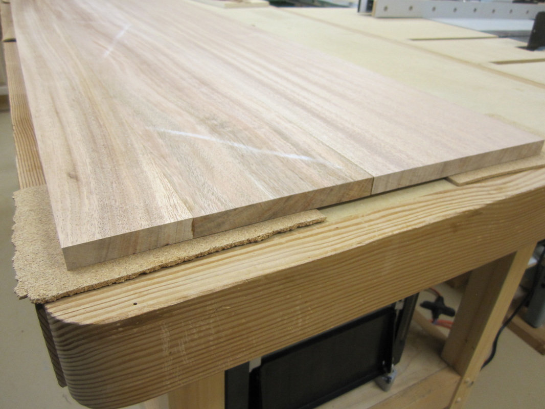
Unfortunately,
after a few days out of the clamps, one of the ends of the dresser top started
to twist and I thought it would compromise the piece, as well as making it
difficult to fit the breadboard ends, if I didn’t replace it. I cut off about
4” strip from the offending side, planed up another piece of stock, trying to
minimize the joint appearance and glue line, re-glued and clamped it. This time
it remained flat and allowed me to continue with the remaining work on the
tops.
|
|
|
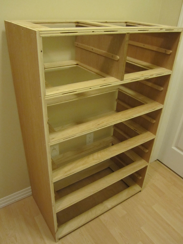
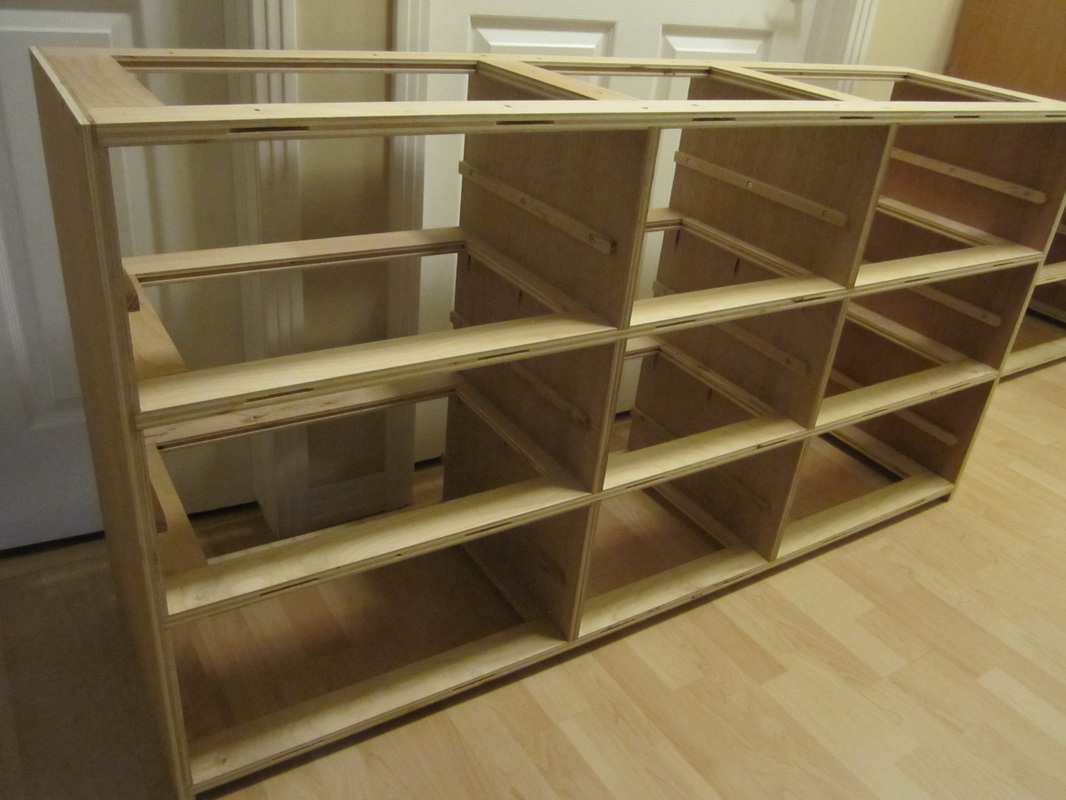
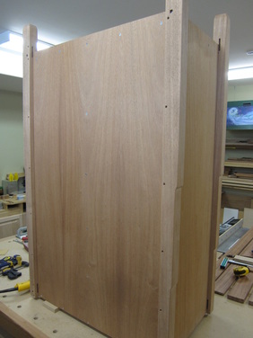
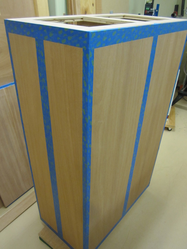
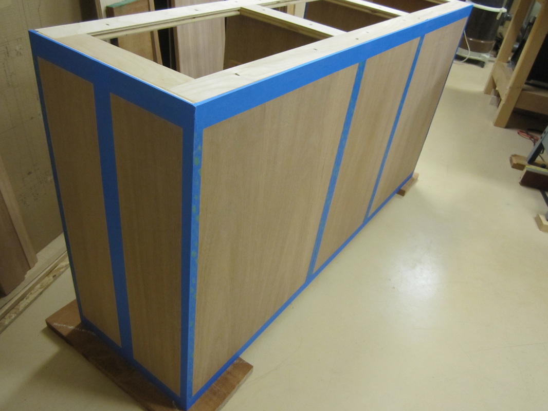
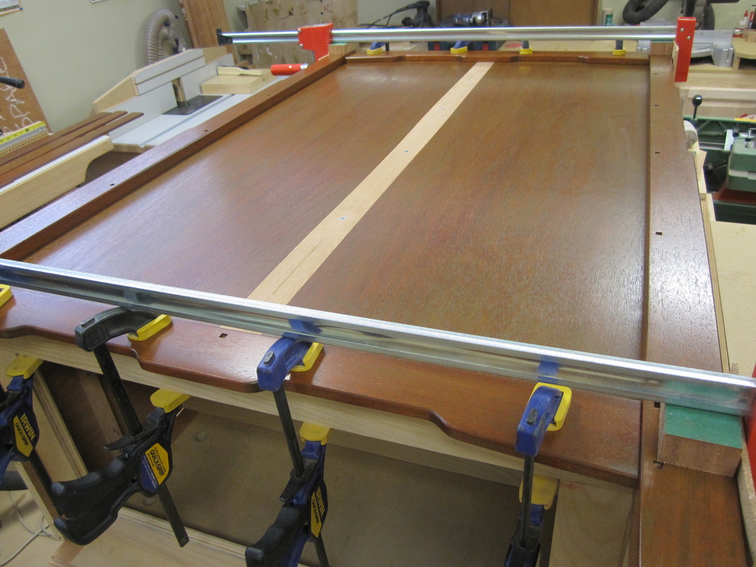
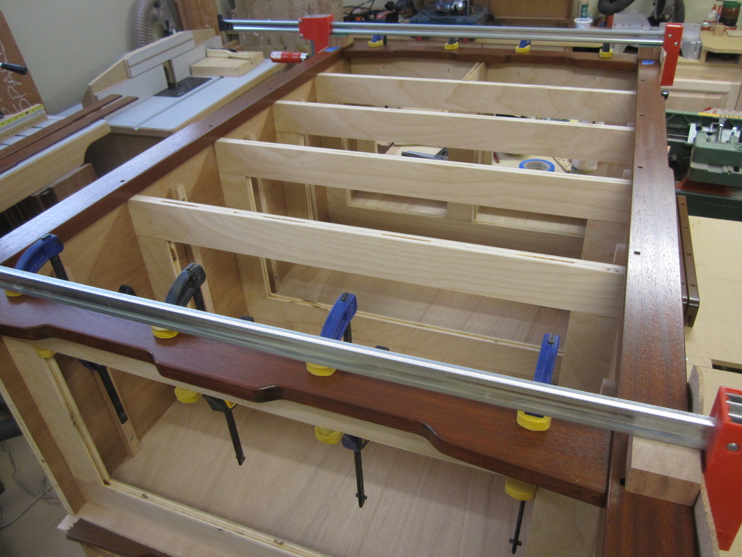
Before continuing with the tops and front and side rails, I decided I should cut and add the plywood back panels to both pieces. I carefully selected a pleasing grain pattern from my plywood material, making the back of the chest from a single piece and the back of the dresser from three pieces. The joints in the dresser back would be covered by decorative pieces applied later, which allowed me to add screws as well as glue for extra strength and to prevent racking. To ensure that the dividers did not sag or move out of place while I was attaching the back panels, I used spacer pieces to keep them parallel. |
|
Next, the glued up blanks for the tops were cut to final length, allowing for the tongues at each end that will fit into the grooves in the breadboard ends.
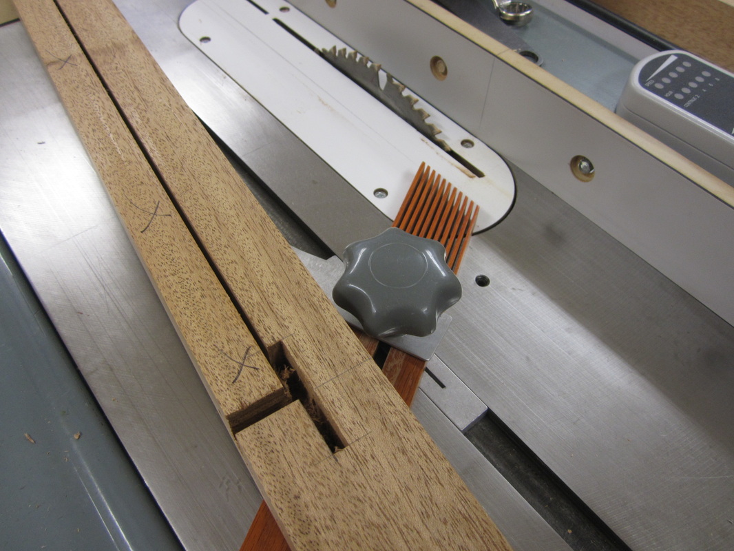
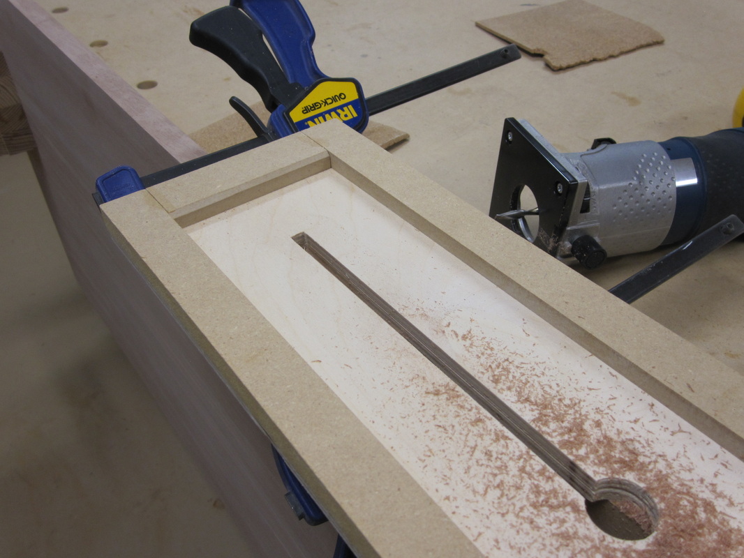
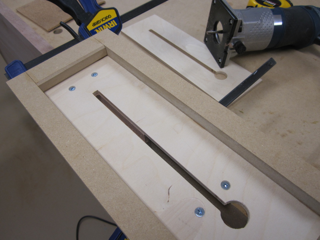
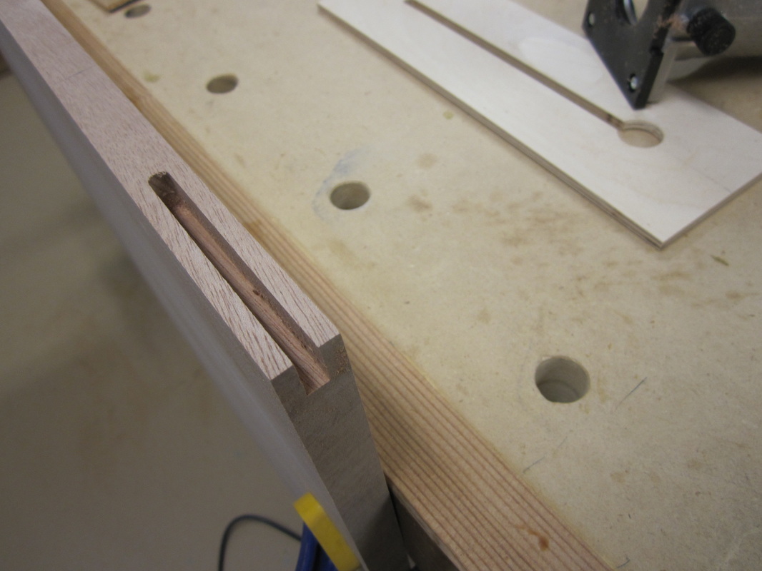
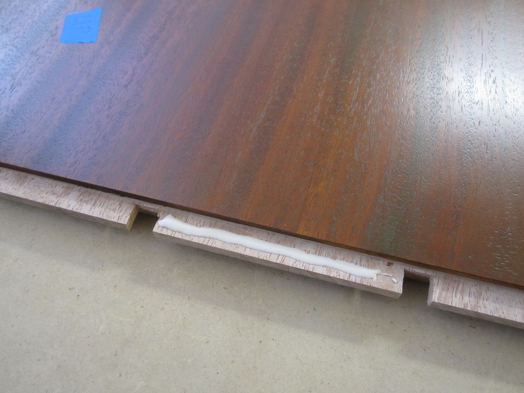
The edges of the tops where they meet the breadboard ends have splines that cover the joints with the breadboard ends and give the illusion that the joint is much deeper than it really is. Using a jig with a removable insert, I cut grooves with my palm router along the edges of the tops adjacent to the ends. The removable insert allowed me to make a second pass with the router to deepen the groove without changing any of the set-up. These grooves are then squared up with a chisel and I also marked the location of the tongues with my marking gauge to minimize the possibility of tear-out when I cut the tongues with the dado blade set at the table saw.
|
Next, I drilled pilot holes at the larger 3/8” square peg locations in the legs for screws that are used to temporarily attach the legs while measurements are marked for the length of the rails and tenons. Then the legs are finish sanded before attaching to minimize errors when marking the shoulders of the tenons on the rails. |
|

|
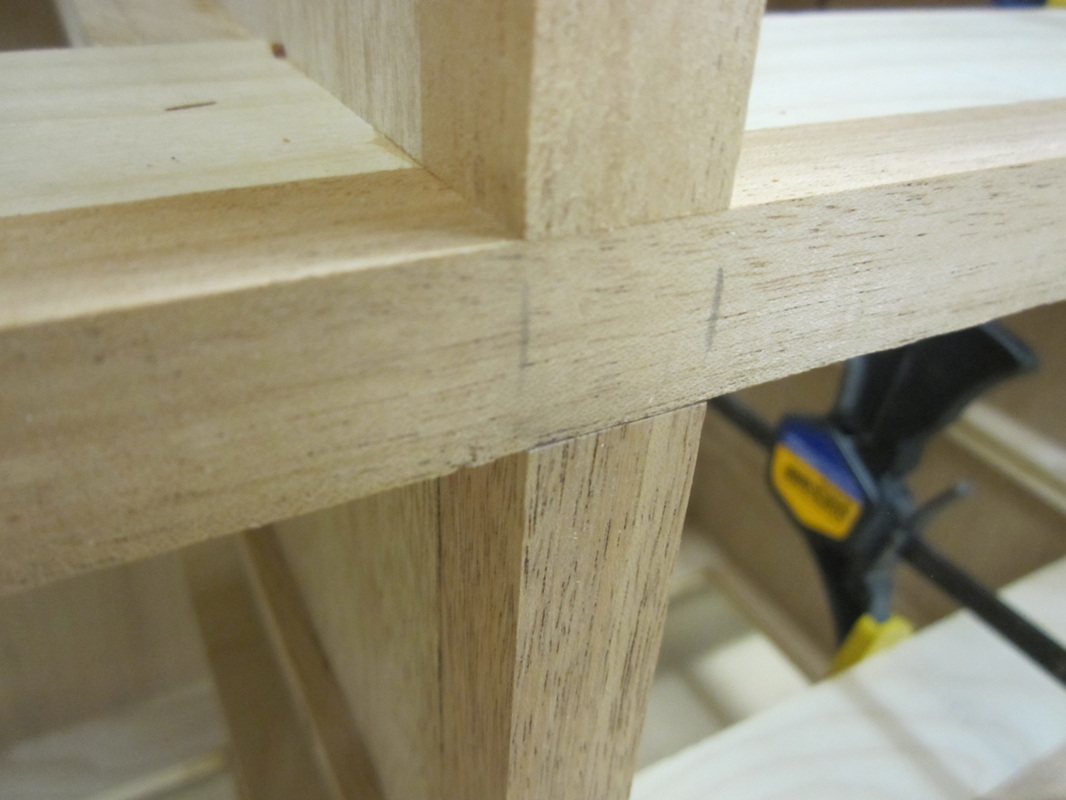
The legs are temporarily attached to the carcass with screws to allow accurate transfer of measurements to the rails for the tenon shoulders. The profiles from the templates are transferred on to the rails and the rough position of the tenons marked, based on the drawing. Minor discrepancies did show up, likely as a result of shrinkage, sanding, or accumulation of tolerances, so the direct transfer method gives a much more accurate joint. 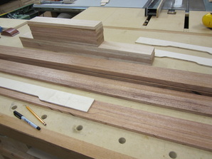
|


Since the tenons on the rails are flush with the back of the rails, I decided to cut them at the radial arm saw and trim them to length using my cross-cut sled and the table saw. I used my shoulder plane to trim for final fitting.
The rails and legs are then dry-fitted to the carcass and held with clamps to check the joinery fits before cutting the profiles in the rails.
Next, the rails are profiled to match the templates, starting with rough cuts at the band saw and then finish trimming with the template and pattern bit at the router table. Again, I used caution by flipping the pattern to the opposite face to avoid making any climb cuts in the profiles which could cause tearing or chip-outs.

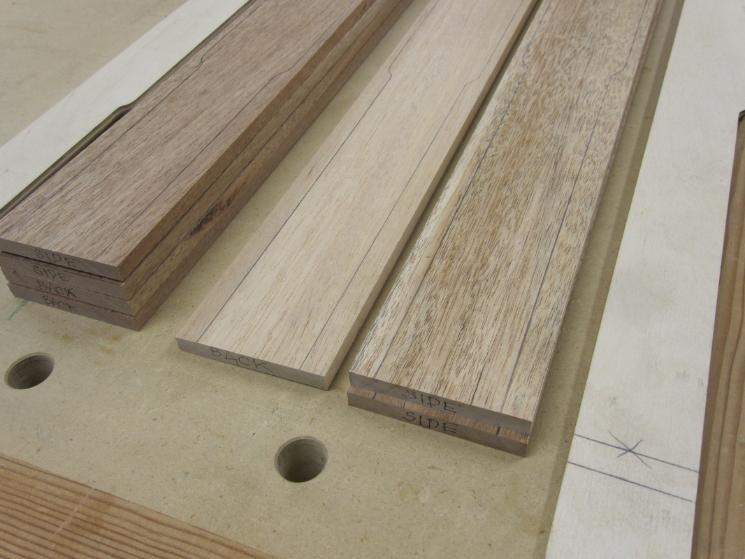
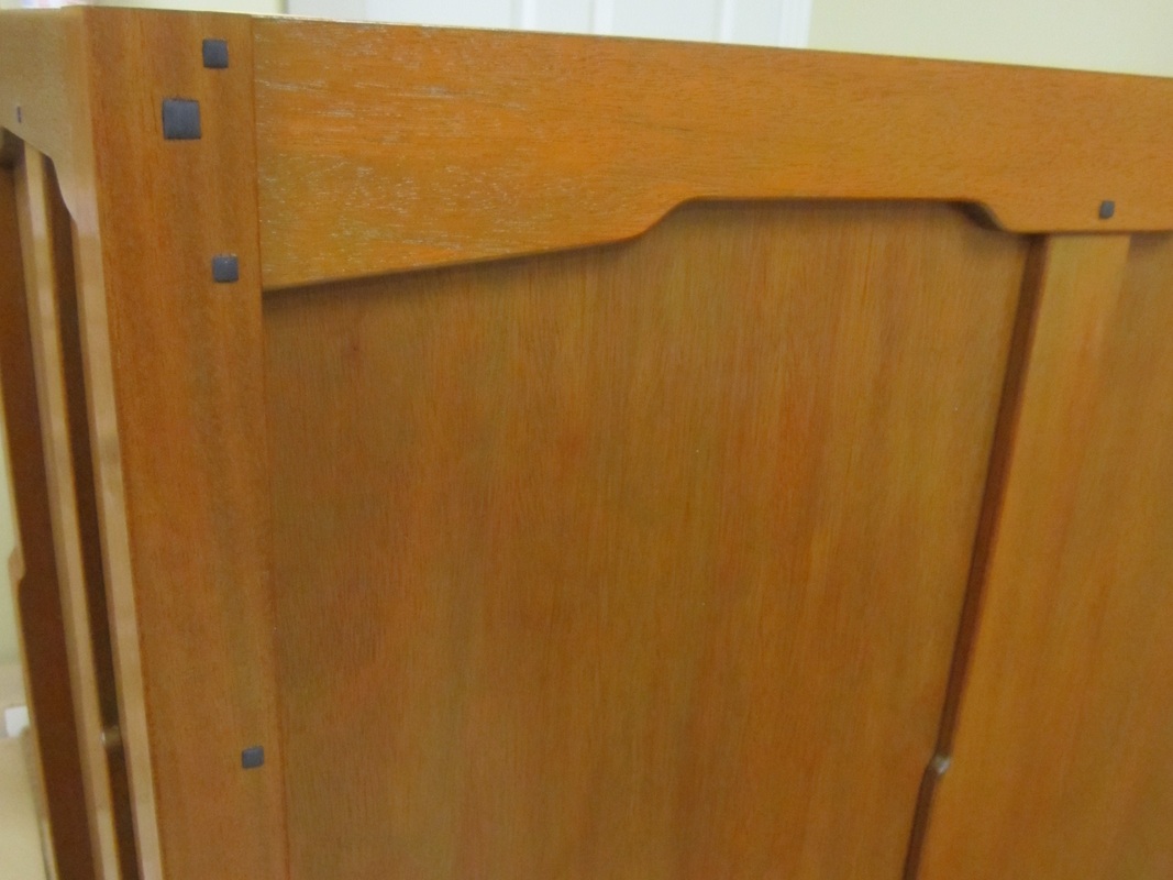
The side panels of each piece have a central panel divider with a similar cloud lift profile to the legs. There is a similar panel divider in the centre of the chest back and three similar panel dividers on the back of the dresser. These ½” thick panel dividers are purely decorative; however, they do hide the screws that are used to secure the back panels to the drawer dividers as well as hiding the joints between the three back panels of the dresser. Again, these pieces are rough cut to profile at the band saw and finish trimmed with the template and pattern bit at the router table. They are cut to final length to fit between the bottom and top rails in their respective positions, with the butt joint measurement directly transferred at the dry-fitted stage.
|
|
Rounding over of all the rails and panel dividers was done at the router table with the 1/8” round-over bit and holes for the square decorative pegs were cut in their respective locations. The holes are cut closer to the bottom of the top rails and closer to the top of the bottom rails to give the illusion that they are securing a mortise and tenon joint. Round-overs are omitted where these parts touch the side or back panels so they will fit closely. |
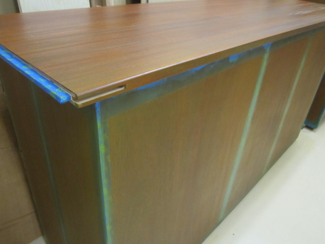
To complete the tops, the breadboard ends are planed to final thickness and cut to length. Centred grooves are cut along one edge of each piece for corresponding tongues that will be cut on the ends of the tops. This is done similarly to the drawer divider frame stock, in two passes, flipping end for end between them, at the table saw. Grooves are also cut along the ends of the breadboard end pieces to accommodate the splines in the same way that was done for the night stand tops. The outside corners are cut and sanded to a pleasing radius and the edges, except for those butting up against the tops, are rounded over at the router table as mentioned previously.
|
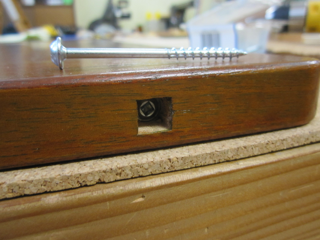
Four square holes are positioned and cut with the mortising machine along the outside edge of each breadboard end piece followed by pilot holes drilled at the drill press for screws that will be used to secure them to the tops. |
|
Tongues to match the grooves in the breadboard ends are rough cut on each end of the tops using the cross-cut sled and dado blade set at the table saw. The fit of the tongues is fine-tuned with the shoulder plane. Small sections of the tongues are removed in places corresponding to the location of the screw pilot holes in the breadboard ends. The breadboard ends are dry-fitted and the pilot holes are extended through into the tops. Only the centre section of the tongues will be glued to the breadboard ends and screws will secure the remainder allowing the top to expand and contract with changes in humidity. The removed sections of the tongue will allow the screws some movement.
After sanding through 120, 180 and 220 grits, all the parts are ready for pre-finishing before further assembly. Those areas of parts that will be glued are masked off to avoid getting stain and finish on them, which would compromise the strength of the joint.

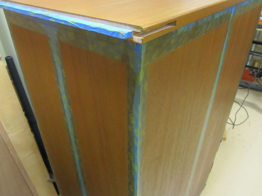
The finishing process is essentially the same as for the bed and night stands, an aniline dye followed by an oil-based colour glaze that mellows the colour and provides the appearance of a patina. The excess colour glaze is wiped off and, after drying, the parts are finished with 3 coats of hand rubbed satin polyurethane, sanding with 320 grit sandpaper before the final coat.
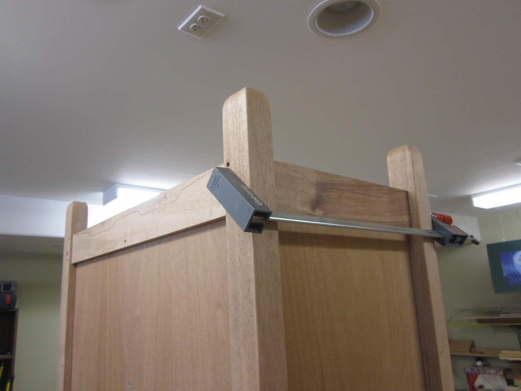
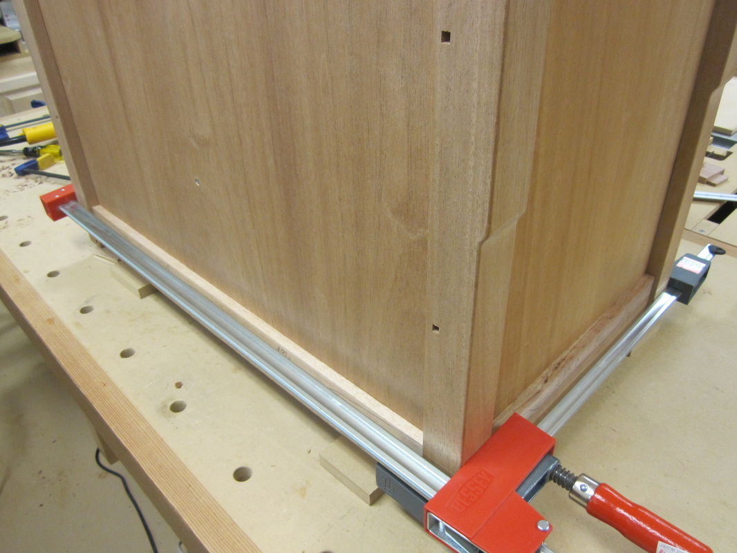
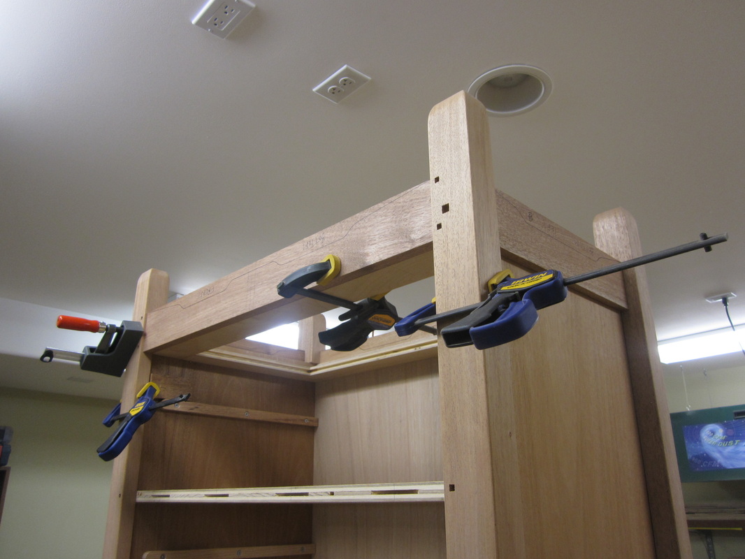
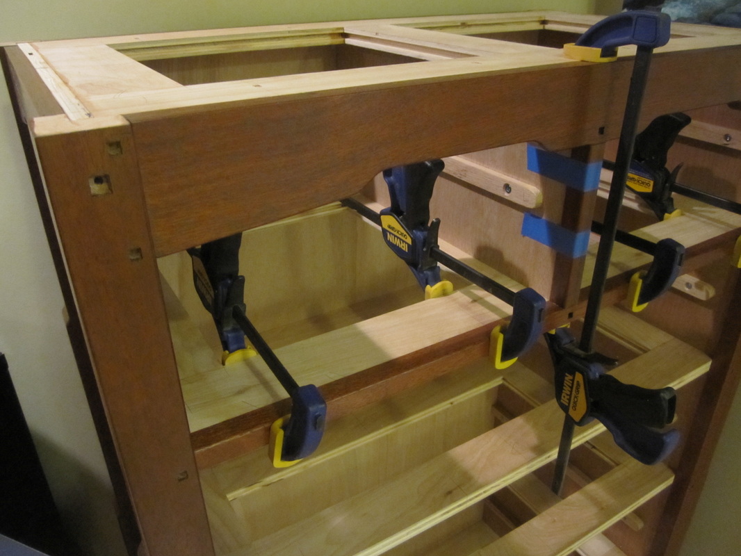
Final assembly begins with gluing the top and bottom rails on to their respective carcasses using the corresponding legs dry-fitted to ensure correct positioning. I try to minimize the amount of parts and joints I glue up at one time because of the risk of the glue drying out before I am satisfied with the joint and the squareness of the piece. The top and bottom rails are glued to the fronts and backs and then the shorter top and bottom rails of the sides are glued up with the legs. Finally these side leg and rail assemblies are glued to the carcasses and the front and back rails.
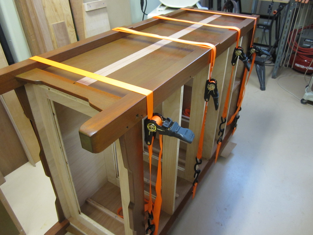
I used band clamps (hold-downs) to hold the whole assemblies together until the glue dries.
I used band clamps (hold-downs) to hold the whole assemblies together until the glue dries.

|
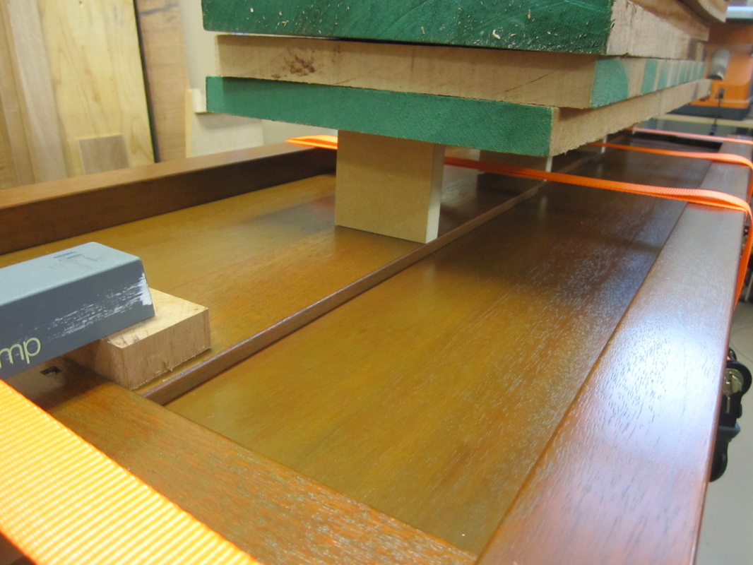
With the top and bottom rails in place, final measurements can be marked directly to cut the panel dividers to length. These are glued over the joints (where used) and screws used to secure the back panels to the drawer dividers. Since they are too far from the edges of the pieces to use clamps, I positioned them carefully and then weighted them down with some of the rough stock for the drawers.
|
|
I noticed after I had assembled all these parts that there was a pronounced difference in the way the plywood panels of the carcasses had absorbed the green oil based glaze and I thought it spoiled the appearance so I stained over them again with a red mahogany gel stain, wiping it off almost immediately. This toned down the green glaze and made the overall appearance more uniform.
Next I attached the breadboard ends to the tops using glue in the centre section only and pocket-hole type screws in all the holes made earlier, which will allow the top to move across the grain due to humidity changes.
Next I attached the breadboard ends to the tops using glue in the centre section only and pocket-hole type screws in all the holes made earlier, which will allow the top to move across the grain due to humidity changes.
|
|
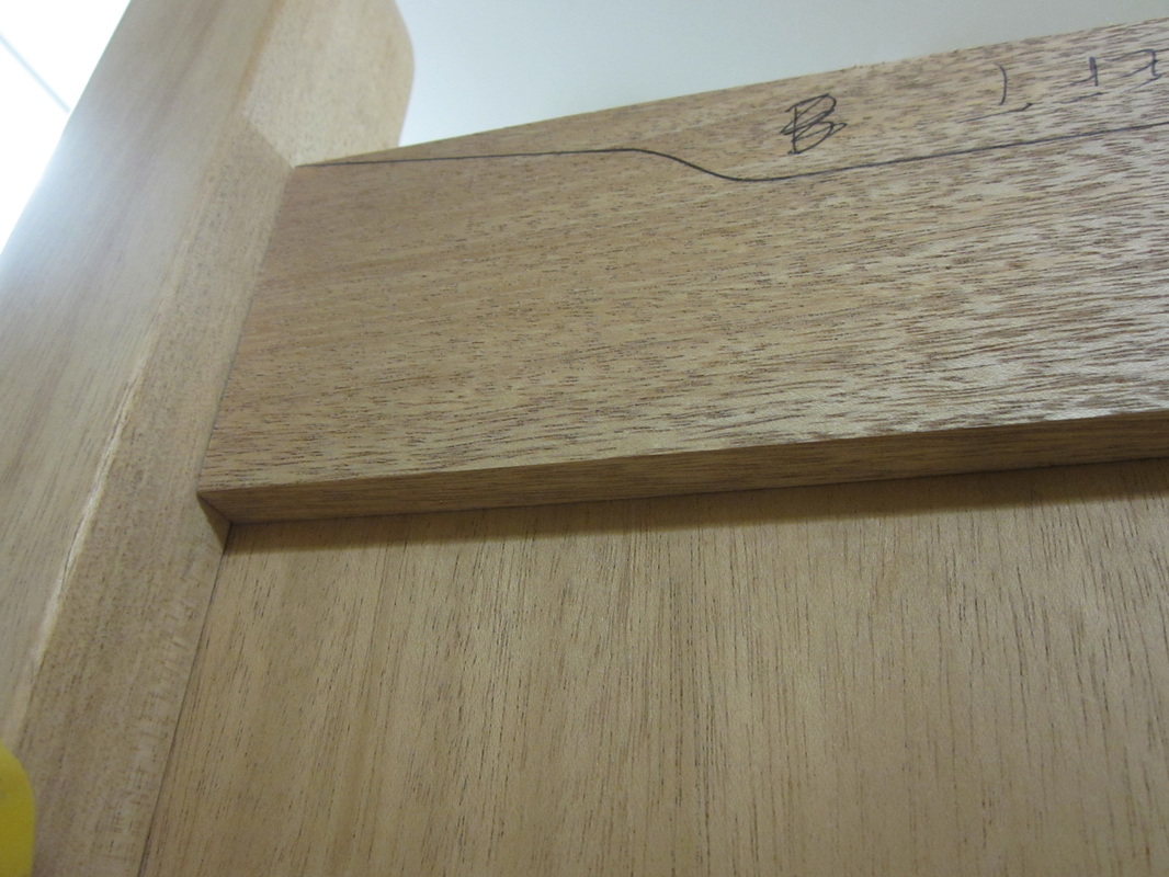
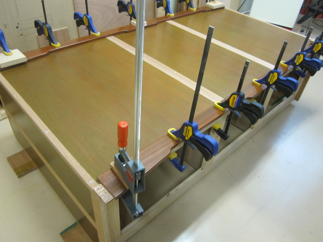
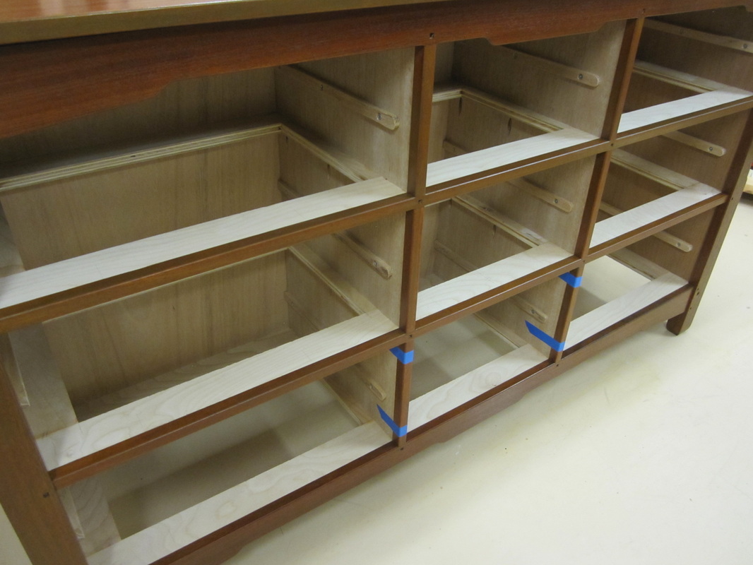
With all the legs and rails in position, final measurements for the mahogany facing of the drawer dividers can be marked directly and cut to size. |
|
Biscuits slots are cut in the backs of these facing pieces to correspond to the slots cut in the fronts of the drawer dividers. Square holes are cut at the intersections for the decorative ¼” pegs. Then they are pre-finished and glued and clamped into place. |
|
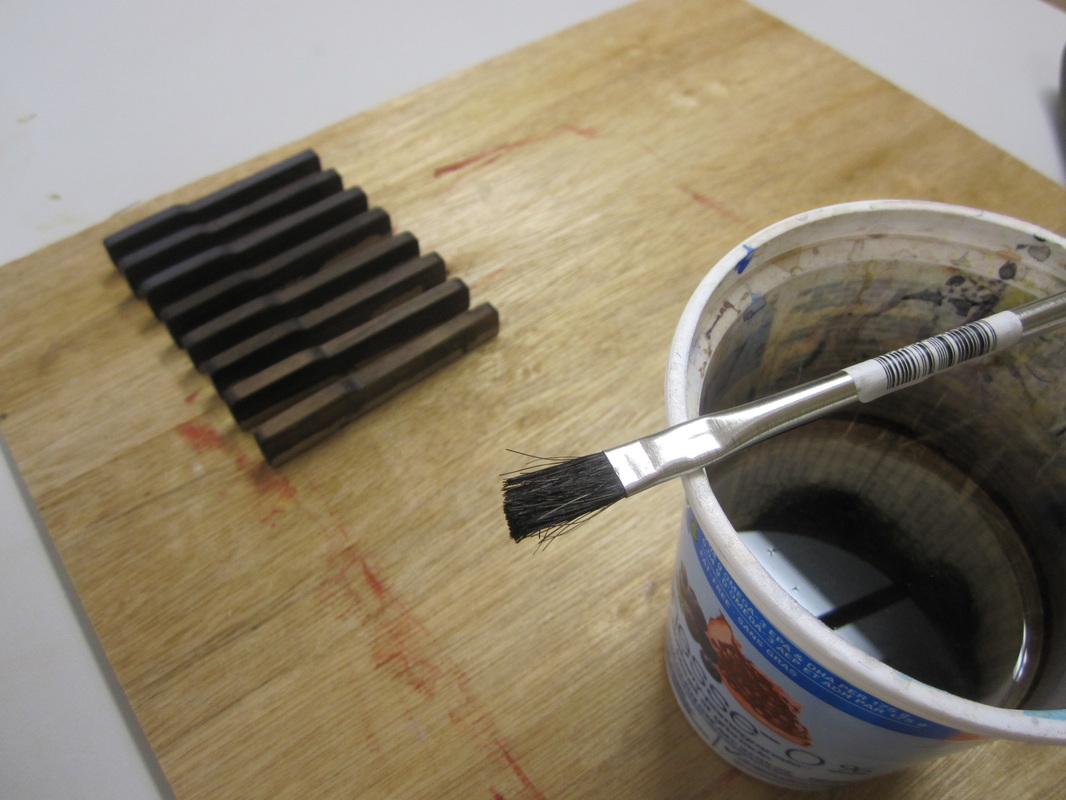
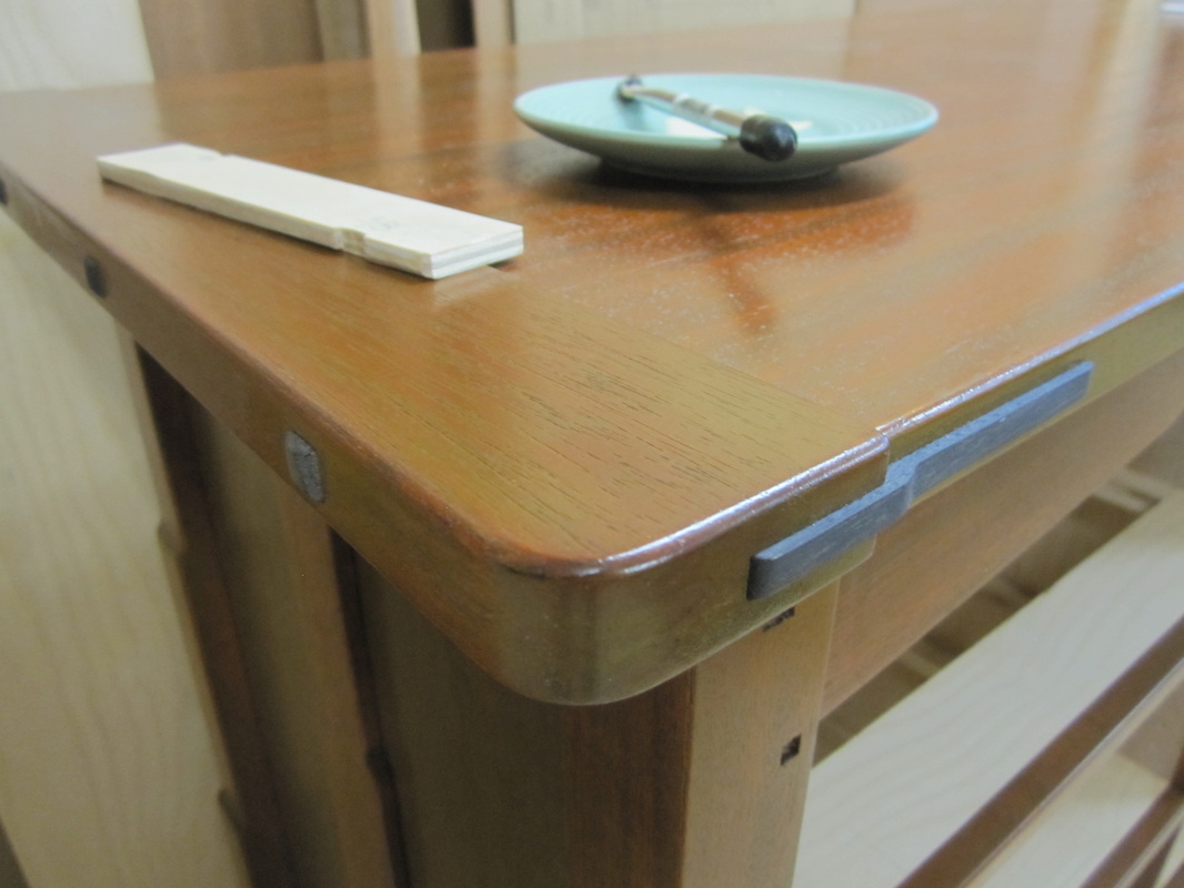
The splines for the breadboard edges of the tops and the decorative pegs are cut from black walnut and ebonized as described in the sections for the bed and night-stands. The splines are glued into the tops only and let to float in the breadboard edges. All the pegs are glued into place using a setting gauge to achieve the desired projection.

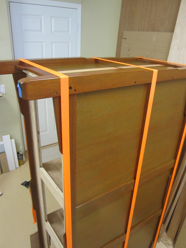
At this point, the carcasses were finished and it was time to move them out of my workshop into the intended location in the bedroom to make space for the construction of the drawers. The final sizing for the drawer components can be measured and marked directly from the completed carcasses to ensure that they all fit correctly.
On to the drawer construction....
On to the drawer construction....